MI_STAR_EN.doc
SR Installation Manual EN
Indice : C
03/05/2019
10 / 15
ERECA SAS 75 rue d'Orgemont, 95210 SAINT GRATIEN France
Tel +33 1 39 89 76 23 www.ereca.fr
1.3 OPTIONAL CONNECTORS / FUSE / PART NUMBER
1.3.1 Description
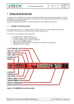
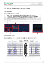
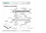
The left part of the Display face provides:
1
Extra SC/APC terminal option (in case of OpticalCon Quad optical connections)
2
12 green LED status of the optional signal transmission (Eg:12 RS422 TX/RX activity)
3
Two D SUB 25 female sockets for the optional signal transmission (Eg:12 RS422)
4
Fuse for PSU1 (2 Amperes Slow Blow 5*20mm fuse)
5
Fuse for PSU2 (2 Amperes Slow Blow 5*20mm fuse)
6
(Video section)
Product information, a STAGE RACER is composed of 1 STAR TX + 1
STAR RX:
1
2
3
4
5
6
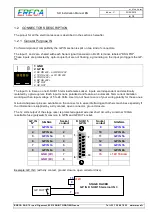
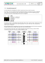
1.3.2 12 RS422 Pinout
One D SUB 25 pin female socket provide the access to the extra RS422 channels 1 to 6.
One D SUB 25 pin female socket provide the access to the extra RS422 channels 7 to 12.
Channel
SIGNAL
Socket
contact
D SUB 25
RS422 1to6 &
RS422 7to12.
Socket
contact
SIGNAL
1 and 7
IN 1/7 -
1
1
25
14
13
14
IN 1/7 +
1 and 7
OUT 1/7 +
2
15
OUT 1/7 -
2 and 8
IN 2/8 -
3
16
IN 2/8 +
2 and 8
OUT 2/8 +
4
17
OUT 2/8 -
3 and 9
IN 3/9 -
5
18
IN 3/9 +
3 and 9
OUT 3/9 +
6
19
OUT 3/9 -
all
GND
7
20
IN 4/10 -
4 and 10
IN 4/10 +
8
21
OUT 4/10 +
4 and 10
OUT 4/10 -
9
22
IN 5/11 -
5 and 11
IN 5/11 +
10
23
OUT 5/11 +
5 and 11
OUT 5/11 -
11
24
IN 6/12 -
6 and 12
IN 6/12 +
12
25
OUT 6/12 +
6 and 12
OUT 6/12 -
13
Pinout is the same for the two connectors. It is strongly recommended to connect the shield of the signals
transmitted to the GND pin.


