background image

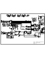
Model : 

GT-X750,Perfection 4490 Photo

Board : Main Board

Rev.

: A

Sheet : 1/1

Содержание Perfection 4490 Photo

Страница 1: ...EPSON Perfection4490Photo AutomaticDocumentFeeder Color Image Scanner Service Manual SESC05004 ...

Страница 2: ...greatly appreciate being informed of them The contents of this manual are subject to change without notice The above not withstanding SEIKO EPSON CORPORATION can assume no responsibility for any errors in this manual or the consequences thereof EPSON is a registered trademark of SEIKO EPSON CORPORATION General Notice Other product names used herein are for identification purpose only and may be tr...

Страница 3: ...TRONIC COMPONENTS 4 WHEN DISASSEMBLING OR ASSEMBLING A PRODUCT MAKE SURE TO WEAR GLOVES TO AVOID INJURIER FROM METAL PARTS WITH SHARP EDGES WARNING 1 REPAIRS ON EPSON PRODUCT SHOULD BE PERFORMED ONLY BY AN EPSON CERTIFIED REPAIR TECHNICIAN 2 MAKE CERTAIN THAT THE SOURCE VOLTAGES IS THE SAME AS THE RATED VOLTAGE LISTED ON THE SERIAL NUMBER RATING PLATE IF THE EPSON PRODUCT HAS A PRIMARY AC RATING D...

Страница 4: ...circuit boards components layout Electrical circuit boards schematics Exploded diagram Parts List Optional part ADF Symbols Used in this Manual Various symbols are used throughout this manual either to provide additional information on a specific topic or to warn of possible danger present during a procedure or an action Be aware of all symbols when they are used and always read NOTE CAUTION or WA...

Страница 5: ...t release B August 31 2005 CHAPTER 4 DISASSEMBLY AND ASSEMBLY 4 2 15 Removing Torsion Spring p49 A caution is added CHAPTER 7 APPENDIX 7 3 Exploded diagram p73 is updated 7 4 Parts List p78 is updated 7 8 ADF Exploded diagram p98 is added 7 9 ADF Parts List p104 is added ...

Страница 6: ...iagnosing 26 3 2 Troubleshooting 27 Chapter 4 Disassembly Assembly 4 1 Overview 30 4 1 1 Precautions 30 4 1 2 Recommended Tools 30 4 1 3 Recommended Screws 30 4 2 Disassembly Procedure 31 4 2 1 Removing the TPU Unit 32 4 2 2 Removing the Upper Housing 33 4 2 3 Removing the Carriage Unit 34 4 2 4 Removing the Panel Board 36 4 2 5 Removing the Main Board 37 4 2 6 Removing the Power Switch 40 4 2 7 R...

Страница 7: ...X 7 1 Connectors 64 7 1 1 Connector Reference Table 64 7 1 2 Connector Configuration 64 7 2 Circuit Diagrams 65 7 3 Exploded diagram 73 7 4 Parts List 78 7 5 Optional Part Auto Document Feeder 79 7 5 1 Overview 79 7 5 2 Basic specifications 79 7 5 3 Interface 81 7 6 ADF Disassembly 82 7 6 1 Removal of B81334 Main Board 82 7 6 2 ASF Part 83 7 6 3 Disassembly of ASF and Frame 89 7 6 4 Disassembly of...

Страница 8: ...C H A P T E R 1 PRODUCTDESCRIPTION ...

Страница 9: ...ssional Mode Stand alone application In addition to TWAIN driver function saving images without using a graphic application such as Photoshop is available Additional image editing tools histogram multi level unsharp mask de screening and tone curve editor Image enhancement functions dust remover photo restoration and grain reduction Full automatic mode flatbed and film Thumbnail view support Suppo...

Страница 10: ...re resolution of 4800 x 9600 dpi is achieved using EPSON s Micro Step Drive technology The motor basic step is 2400 dpi Output Resolution 50 to 6400 dpi in 1 dpi increments 9600 dpi 12 800 dpi Speed color 16 832 msec line at 4800 dpi in Draft mode Pixel depth 16 bits per pixel input and output Command level ESC I D2 FS Interfaces USB 1 1 2 0 Light source White cold cathode fluorescent lamp Reliabi...

Страница 11: ...13 to 140 F 25 to 60 C Humidity non condensing Operation 10 to 80 ADF 20 to 80 Storage 10 to 85 OPERATING CONDITIONS Ordinary office or home conditions avoid extreme dust direct sunlight and strong light sources EMC AND SAFETY STANDARDS COMPLIANCE Scanner 100 V FCC15B Class B USA CSA108 8 Class B Canada FCC represents 200 V EN55022 CISPR Pub22 Class B EN61000 3 2 EN61000 3 3 EN55024 AS NZS3548 Cla...

Страница 12: ...tion Revision 2 0 Vendor ID 04B8h Product ID 0119h Connector type One self powered receptacle Type B Must be connected directly to the host or to tier 1 in a hub with a recommended USB cable Interface Operating System USB 1 1 I F Microsoft Windows 98SE Me 2000 Professional XP Home Edition XP Professional Pre installed model or upgrade of Windows 98 Me 2000 Professional pre installed model Mac OS X...

Страница 13: ... stores the sccanned data 1 5 2 Explanation of LED Indicators Status LED Located to the left of the Start Button Indicates scanner statuses with a green or red light as shown in the table below Note 1 Warm up scanning initializing etc 2 Certain error conditions such as Option Error may not cause the Status LED to turn red Figure 1 2 Switches and LEDs LED Indication Status Lit Green Ready Flashing ...

Страница 14: ...terior Specifications 14 1 5 3 Dimensions Dimensions and Weight Dimensions 272 x 475 x 113mm W x D x H Weight Approx 4 0 kg without AC adaptor 4 113 kg with AC adaptor External Drawing Figure 1 3 External Dimensions of Perfection 4490 Photo Unit mm 70 113 272 475 ...

Страница 15: ...e 8 5 in 216 mm W x 11 7 in 297 mm H Figure 1 4 Reflective Document Scanning Range TRANSPARENT DOCUMENT Size 2 72 in 68 mm W x 9 44 in 236 mm H Figure 1 5 Transparent Document Scanning Range 8 5 in 216 mm 1 0 5 mm 1 6 0 5 mm 11 7 in 297 mm Scanning home position Front 2 72 in 68 mm 67 56 1 5 mm 13 48 1 5 mm 9 44 in 236 mm Front Scanning home position ...

Страница 16: ...scan start FS G Data form setting Data format setting ESC D i Resolution setting ESC R n1 n2 Scanning area setting ESC A n1 n2 n3 n4 Color setting ESC C i Parameter setting FS W Correction Processing Gamma correction setting ESC Z i Gamma correction table setting ESC z i d 256 Image Processing Threshold value setting ESC t I Support and Miscellaneous Scan mode setting ESC g i Initialization ESC Li...

Страница 17: ...er interpreter ignores the incorrect command or parameter Current setting maintained The Scanner interpreter returns NACK and waits for the next command parameter The error condition is cleared when the scanner interpreter receives a valid command Fatal error Red LED flashes rapidly The lamp is burnt out The main unit is faulty Firmware downloading failed The Scanner turns the carriage lamp off an...

Страница 18: ...C H A P T E R 2 OPERATINGPRINCIPLES ...

Страница 19: ...s color CCD R G B independent and its control and drive circuits Inverter Board Boosts 24VDC and converts DC to AC to generate the voltage for driving the Lamps white cool cathode fluorescent lamps Lamps White cool cathode fluorescent lamps are used as a light source When the amount of light is not stable the Panel LED flashes and enter the standby mode until it becomes stable Mirror Lens Mechanis...

Страница 20: ...ge Unit Configuration Inverter Board converts DC to AC and boosts the voltage to generate the current necessary to power the Lamps Lamps used as the primary light source are white cool cathode fluorescent lamps If the light output becomes unstable the Panel LED flashes and the scanner enters standby mode until it becomes stable SUB_C Board and SUB_D Board each contain LEDs to generate infrared lig...

Страница 21: ... moved by CR drive The scanned data are sent to the Control Board The scanning of Line n data and the processing of Line n 1 image data are performed consecutively at the same time Figure 2 4 Carriage Movement The Carriage Unit slides along the guide rail in the sub scanning direction To perform this sliding operation the CR Carriage Motor transmits its drive power to the Timing Belt which is fixe...

Страница 22: ... the secondary scanning direction as the TPU CR Carriage Motor transmits its drive power to the TPU CR Drive Belt connected to the TPU Carriage Unit via the Idle Pulley and Drive Pulley Refer to Fugure 2 6 The TPU CR Motor uses a stepper motor and is driven under open loop control Figure 2 6 TPU Carriage Operation Front Rear Drive Pulley Idle Pulley TPU CR Drive Belt TPU Carriage Unit ...

Страница 23: ...ically remove it using interpolated image data to overwrite and correct the image Because of the difference in wavelength between infrared light and visible light a secondary lens Glass Plate in the images below must be employed during the Film ICE visible light scan to compensate for the resulting difference in the size of the images so that they can be superimposed accurately The Glass Plate is ...

Страница 24: ...PU Unit ADF Board Option Table 2 1 Main Board IC Name Location Details S1R77001F00A2 IC4 ASIC Host base scanner controller S1R720G0F00A0 IC6 ASIC UTM USB2 0 interface EDS6416AHTA 75 E IC3 SDRAM 1M x16bit x4bank TB62205F IC1 Motor Driver DC DC converter CR Motor Drive 24V IN 12V 5V OUT AP1120SLA IC2 DC DC converter 5V IN 3 3V 2 5V OUT M74HC595AM13TR IC5 Serial Parallel converter Table 2 2 CCD Board...

Страница 25: ...C H A P T E R 3 TROUBLESHOOTING ...

Страница 26: ...and ESC e Table 3 1 Command Error LED Indication Cause Disposition Unidentifed command is detected The scanner interpreter ignores the incorrect command or parameter The current settings are maintained Scanner interpreter returns NACK and waits for the next command or parameter Recovery The error condition is canceled upon receipt of a valid command Table 3 2 Fatal error LED Indication Cause Dispo...

Страница 27: ...2 Table 3 5 Scanned Image Quality Error Step Possible Cause Corrective Action 1 The Document Glass is not clean Image has white spots Clean the glass Refer to 6 1 1 Cleaning 2 The mirror in the Carriage is not clean Vertical bands appear on the image Clean the mirror Refer to 6 1 1 Cleaning 3 Upper Housing failure The white document mat is deformed or is not clean Replace the Upper Housing 4 CCD S...

Страница 28: ...to the main unit 2 Connector CN5 is not connected to the Main Board Connect it correctly 3 Main Board failure Replace the Main Board Table 3 11 The TPU Carriage Unit does not operate Step Possible Cause Corrective Action 1 The TPU Unit Cable is not connected to the main unit Connect the TPU Cable to the main unit 2 The TPU Carriage Lock has not been released Release the TPU Carriage Lock 3 The TPU...

Страница 29: ...C H A P T E R 4 DISASSEMBLY ASSEMBLY ...

Страница 30: ... or reassembly C A U T I O N When touching any internal components use static electricity discharge equipment such as anti static wrist straps Provide sufficient work space for disassembling and reassembling Always use only the recommended tools for disassembly reassembly and adjustment Be sure to tighten the screws to the specified torque Use the specified grease for lubrication Refer to Chapter ...

Страница 31: ...lowchart Start Removing the TPU Unit P 32 Removing the Upper Housing P 33 Removing the Carriage Unit P 34 Removing the Panel Board P 36 Removing the Main Board P 37 Removing the Driven Pulley Driven Pulley Spring and the Driven Pulley Holder Assy P 42 Removing the Power Switch P 40 Removing the CR Motor Unit Motor Tension Belt and the CR Tension Belt P 43 Removing the Panel FFC P 41 Removing TPU L...

Страница 32: ...rocedure 32 4 2 1 Removing the TPU Unit 1 Disconnect the TPU Unit cable from the Main Unit Figure 4 2 Removing the TPU Unit 1 2 Open the TPU Unit 3 Hold both ends of the TPU Unit and then lift and remove it Figure 4 3 Removing the TPU Unit 2 TPU Unit Cable Main TPU Unit 2 3 ...

Страница 33: ...rocedure 33 4 2 2 Removing the Upper Housing 1 Remove the TPU Unit See Section 4 2 1 on page 32 2 Remove the four C B P M3 x 8 screws that secure the Upper Housing to remove it Figure 4 4 Removing the Upper Housing Viewed from the outside Upper Housing C B P 3 x 8 7 1 kgf cm ...

Страница 34: ...to the front of the main unit Figure 4 6 Moving the Carriage Unit 4 Disconnect the Carriage FFC from the Main Board See Section 4 2 5 Step 5 Step 7 5 Remove the two sided tape that secure the Carriage FFC to the Upper Housing 6 Remove the Ferrite Core from the Carriage FFC Figure 4 7 Removing the Carriage FFC Carriage Lock Unlock Lock Carriage Unit 3 Secure the Carriage FFC with a piece of two sid...

Страница 35: ... Shaft from the rear bushing of the Lower Housing then pull the other end out of the front bushing of the Lower Housing 9 Remove the Carriage Shaft from the Carriage Unit Figure 4 9 Removing the Carriage Shaft 10 Push up the B part of the Lock Plate attached on the rear of the Carriage Unit to remove the Lock Plate from the Carriage Unit Figure 4 10 Removing the Carriage Unit Driven Pulley Holder ...

Страница 36: ...e Panel Board Ground Cable Positioning Holes Front Bushing 2 Notch Panel Board 3 Constricted Parts and Tabs Notch CN1 When reinstalling the Panel Board pay attention to the followings Put the ground terminal into the front bushing of the Lower Housing as shown in Figure 4 11 Route the ground cable through the notches as shown in Figure 4 11 Insert the two constricted parts on both left and right e...

Страница 37: ... 4 Remove the Carriage Lock from the Lower Housing Figure 4 12 Removing the Carriage Lock 5 Remove the Main Board Cover in the following procedure 1 Remove the C B P M3 x 8 screw and C B P M3 x 12 screws that secure the Main Board Cover 2 Remove the two C B P M3 x 8 screw that secure the Main Board from the rear of the main unit Figure 4 13 Removing the Main Board Cover 1 Carriage Lock Rear of the...

Страница 38: ...Board Cover 4 Slide the Main Board Cover in the direction of the arrow to release it from the two tabs and remove the Main Board Cover Figure 4 14 Removing the Main Board Cover 2 3 1 Tab 4 Tab 3 2 Main Board Cover When reinstalling the Main Board Cover match the two tabs and two interfaces with the holes of the Main Board Cover as shown below Figure 4 15 Installing the Main Board Cover I F Tabs ...

Страница 39: ... the four C B P M3 x 8 screws that secure the Main Board 7 Disconnect the all connectors on the Main Board and remove the Main Board CN1 Carriage FFC CN2 CR Motor Cable CN3 Power Switch Connector CN6 Panel FFC Figure 4 16 Removing the Main Board CN1 Main Board CN2 CN3 CN6 C B P 3 x 8 7 1 kgf cm ...

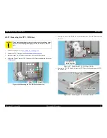
Страница 40: ...3 Remove the Power Switch Connector Cable from the cable trench Figure 4 17 Removing the Power Supply Cable Cover 4 Push the Power Switch toward the outside while releasing the two tabs and remove the Power Switch by pushing it out through the hole on the Lower Housing Figure 4 18 Removing the Power Switch When reinstalling the Power Switch route the Power Switch Connector Cable through the cable ...

Страница 41: ... Move the Carriage Unit to its home position and remove the two sided tape that secure the Panel FFC 4 Disconnect the Panel FFC from CN1 Connector on the Panel Board Figure 4 19 Removing the Panel FFC Carriage Unit 4 CN1 Panel Board 3 Panel FFC Tape Position When installing the Panel FFC attach the Ferrite Core as shown in the figure below Figure 4 20 Installing the Ferrite Core Secure the Panel F...

Страница 42: ...er Assy and slide it in the direction of the arrow to remove the assy from the two tabs on the Lower Housing Figure 4 21 Removing the Driven Pulley Holder Assy 3 Remove the Driven Pulley Spring from the Driven Pulley Holder Assy 4 Remove the washer and remove the Driven Pulley from the shaft of the Driven Pulley Holder Assy Figure 4 22 Removing the Driven Pulley and the Driven Pulley Spring Tabs D...

Страница 43: ...e CR Motor Unit CR Motor Unit Positioning Hole and Guide Pin CN2 C B P 3 x 8 7 1 kgf cm Ground Plate Install the ground plate in the following procedure 1 Match the positioning hole of the ground plate with the guide pin of the Lower Housing 2 Place the CR Motor Unit as shown in the figure below and secure the CR Motor Unit and the ground plate to the Lower Housing When installing the CR Motor Uni...

Страница 44: ... Remove the Motor Tension Belt and the CR Tension Belt from the CR Motor Unit in that order Figure 4 25 Removing the Motor Tension Belt and the CR Tension Belt A D J U S T M E N T R E Q U I R E D When installing the Tensioner make sure to perform the Tensioner Adjustment See Section 5 1 2 1 on page 58 Torsion Spring Tensioner Pulley Motor Tension Belt CR Tension Belt C B 3 x 3 6 1kgf cm ...

Страница 45: ...ge Lock Figure 4 26 Removing the Housing Mat Document Cover 4 Remove the six C B P M3 x 12 screws and the two C B P M3 x 8 screws that secure the TPU Lower Housing Figure 4 27 Removing the TPU Lower Housing 1 5 Lift the rear hinge side of the TPU Lower Housing and slide it in the direction of the arrow to release the two tabs and remove the TPU Lower Housing Figure 4 28 Removing TPU Lower Housing ...

Страница 46: ...e Sensor Board 3 Disconnect the Sensor Connector CN1 while lifting the Sensor Board and remove the Sensor Board Figure 4 29 Removing the Sensor Board 4 2 12 Removing the Hinge Assy 1 Remove the TPU Lower Housing See Section 4 2 10 on page 45 2 Remove the four C B P M4 x 12 screws that secure the left and right Hinge Assy s and remove them Figure 4 30 Removing the Hinge Assy Sensor Board C B P 3 x ...

Страница 47: ...isconnect the TPU Unit Connector CN1 from the DRV Board 5 Release the TPU Unit Cable from the notches shown in the figure below Figure 4 31 Removing the TPU Unit Cable 2 Notches Cable Tie DRV Board CN1 TPU Unit Cable C B P 3 x 8 7 1kgf cm When installing the TPU Unit Cable put the cable and the cable tie into the notches as shown in Figure 4 31 When connecting the TPU Unit Cable to the DRV Board r...

Страница 48: ...n page 45 2 Remove the two C B P M3 x 8 screws that secure the DRV Board Cover and remove the ground to remove the DRV Board Cover Figure 4 33 Removing the DRV Board 1 3 Disconnect the all connectors on the DRV Board and remove the DRV Board CN1 TPU Unit Cable CN2 TPU Motor Connector CN4 Sensor CN3 DRV Inverter FFC Ground CN1 CN4 C B P 3 x 8 CN2 DRV Board Cover CN3 ...

Страница 49: ...le of the mass production for reducing costs Because of that the number of the torsion springs to be installed and how they are attached differ for the late products Make sure to read the technical information TE05 0371 before performing the following work 2 1 TPU CR Drive Belt TPU Driven Pulley 2 2 A D J U S T M E N T R E Q U I R E D To adjust the tension of the TPU CR Drive Belt attach the three...

Страница 50: ...U Carriage Unit Figure 4 37 Removing the DRV Inverter FFC C A U T I O N When performing the procedure given below be careful not to lose the three torsion springs that apply tension to the TPU CR Drive Belt C A U T I O N When performing the next step be careful not to lose the flat washer that secures the Driven Pulley TPU CR Motor Assy TPU CR Drive Belt Flat Washer Drive Pulley TPU Carriage Unit ...

Страница 51: ...rter FFC Figure 4 38 Removing the DRV Inverter FFC 4 Release Connector Cables from the tabs of the Carriage Frame shown in the figure below 5 Disconnect the all connectors CN2 CN3 CN4 from the TPU Inverter Board 6 Remove the C B P M3 x 8 screw that secures the TPU Inverter Board 7 Lift the TPU Inverter Board to release it from the tab of the TPU Carriage Frame and remove the TPU Inverter Board Fig...

Страница 52: ... the guide pins as shown in the figure below When connecting CN2 and CN3 Connector Cables route them under the tab DRV Inverter FFC Tab as shown in the figure below Figure 4 41 Routing the DRV Inverter Cables When connecting the DRV Inverter FFC to the TPU Inverter Board put the FFC through the tab DRV Inverter FFC Tab as shown in Figure 4 38 Secure the DRV Inverter FFC with a piece of acetate tap...

Страница 53: ...following procedure 1 Pull up the A tabs and slide each of the SUB_C and SUB_D Boards in the direction of the arrows 3 1 2 Slide the SUB_C and SUB_D Boards in the direction of the arrows 3 2 and release them from the B tabs to remove the boards Figure 4 42 Removing the SUB_C Board and SUB_D Board 4 Remove the two C B P M3 x 6 screws that secure the TPU Lamp Cover to remove it Figure 4 43 Removing ...

Страница 54: ...4 Removing the Lamp Tabs Lamp When installing the SUB_C Board and SUB_D Board match the notches and tabs as shown in Figure 4 42 When installing the TPU Lamp Cover match the positioning holes and the guide pins as shown in the figure below Route the Lamp cables as shown in the figure below Figure 4 45 Routing the Lamp Cables Positioning Hole and Guide Pin Lamp Cables ...

Страница 55: ...n Figure 4 46 Figure 4 46 Removing the TPU CR Motor Connector 5 Remove the three C P F P M3 x 8 screws that secure the TPU CR Motor Unit and remove it Figure 4 47 Removing the TPU CR Motor Unit 1 6 Remove the TPU CR Drive Belt from the TPU Driven Pulley and remove the TPU CR Motor Unit Figure 4 48 Removing the TPU CR Motor Unit 2 C A U T I O N When performing the procedure given below be careful n...

Страница 56: ...e 4 49 Removing the TPU CR Motor Dampers and TPU CR Motor C A U T I O N When performing the next step be careful not to lose the flat washer that secures the Driven Pulley and Idle Pulley Idle Pulley Driven Pulley Flat Washer C B 3 x 5 9 1kgf cm TPU CR Motor Dampers Route the TPU CR Motor Cables through the groove and notches as shown in the figure below Figure 4 50 Routing the TPU CR Motor Cables...

Страница 57: ...C H A P T E R 5 ADJUSTMENT ...

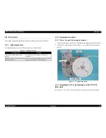
Страница 58: ...Install the Torsion Spring as shown in Figure 5 1 to secure the Tensioner under tension Figure 5 1 Tension Adjustment 5 1 3 Adjustment of Torsion Springs on the TPU CR Drive Belt See Section 4 2 15 on page 49 for information on how to adjust the torsion springs Table 5 1 Adjustment Item Adjustment Item Condition Adjustment of Motor Tension Belt tension When the Motor Tension Belt is removed or loo...

Страница 59: ...C H A P T E R 6 MAINTENANCE ...

Страница 60: ...letely wipe it with a dry clean cloth again Scanner inside Before reinstall the Upper Housing after it had been removed make sure to remove the dust inside of the scanner and the Upper Housing Squirt them with plenty of air 6 1 2 Lubrication Lubrication is required when any part of the Carriage Unit of the scanner has been replaced or the Carriage moves with noticeably large operation noise The sp...

Страница 61: ...rication Point Shaft of the Driven Pulley Lubrication Type G 26 Lubrication Amount Adequate dose Remarks Use a brush to apply it Applying Point Applying Point Driven Pulley Holder Assy Lubrication Point Concave portion of the Carriage Lock Lubrication Type G 26 Lubrication Amount Adequate dose Remarks Use a brush to apply it Lubrication Point A Idle Pulley shaft on the TPU CR Motor Assy B Driven P...

Страница 62: ...pper Housing Lubrication Point Carriage guide rail on the TPU Lower Housing Lubrication Type G 26 Lubrication Amount Adequate dose Remarks Use a brush to apply it Lubrication Point Carriage guide rail on the TPU Upper Housing Lubrication Type G 26 Lubrication Amount Adequate dose Remarks Use a brush to apply it Applying Point Applying Point ...

Страница 63: ...C H A P T E R 7 APPENDIX ...

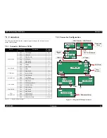
Страница 64: ...2 0 4 Panel Board CN1 Main Board 7 CN2 GND CCD Board CN1 Main Board 29 CN2 Inverter Board 2 CN3 Sensor Board 2 Inverter Board CN1 CCD Board 2 CN2 Fluorescent Lamp 4 2 1 DRV Board CN1 Main Board 8 CN3 TPU Inverter Board 5 CN4 TPU CR Motor 4 CN5 Sensor Board 4 Sensor Board CN1 DRV Board 4 TPU Inverter Board CN1 DRV Board 5 CN2 SUB_C Board 2 CN3 SUB_D Board 2 CN4 Fluorescent Lamp 4 2 1 CCD Board Pane...

Страница 65: ...ision B APPENDIX Circuit Diagrams 65 7 2 Circuit Diagrams The control electrical circuit diagrams of this product are shown on the following pages Main Board Panel Board DRV Board Image Sensor Board SUB Board SUB_C Board SUB_D Board ...

Страница 66: ...Model GT X750 Perfection 4490 Photo Board Main Board Rev A Sheet 1 1 ...

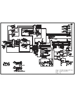
Страница 67: ...Model GT X750 Perfection 4490 Photo Board PNL Board Rev A Sheet 1 1 Model GT X750 Perfection 4490 Photo Board PNL Board Rev A Sheet 1 1 ...

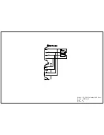
Страница 68: ...Model GT X750 Perfection 4490 Photo Board DRV Board Assy Rev A Sheet 1 1 ...

Страница 69: ...Model GT X750 Perfection 4490 Photo Board Image Sensor Board Rev B Sheet 1 1 ...

Страница 70: ...Model GT X750 Perfection 4490 Photo Board SUB Board Rev A Sheet 1 1 ...

Страница 71: ...Model GT X750 Perfection 4490 Photo Board SUB C Board Rev A Sheet 1 1 ...

Страница 72: ...Model GT X750 Perfection 4490 Photo Board SUB D Board Rev A Sheet 1 1 ...

Страница 73: ...rfection 4490 Photo Revision B APPENDIX Exploded diagram 73 7 3 Exploded diagram The exploded diagrams of this product are shown on the following pages B176 ACCE 0012 B176 CASE 0012 B176 CASE 002 B176 MECH 001 ...

Страница 74: ...GT X750 Perfection 4490 Photo NO 1 Rev 02 B176 ACCE 0012 10 20 30 40 400 401 ...

Страница 75: ...GT X750 Perfection 4490 Photo NO 2 Rev 02 B176 CASE 0012 529 528 524 203 522 528 525 525 115 115 108 113 113 113 106 105 107 201 113 109 100 112 104 114 103 525 519 202 518 517 523 ...

Страница 76: ...R ev 01 B176 CAS E 002 GT X750 Perfection 4490 Photo NO 3 110 111 101 102 ...

Страница 77: ...512 514 500 526 505 515 505 200 513 503 501 502 516 508 510 506 509 511 507 527 504 509 R ev 01 B176 ME CH 001 GT X750 Perfection 4490 Photo NO 4 ...

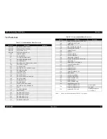
Страница 78: ...R DOCUMENT 112 HOUSING ASSY UPPER ASP 113 FOOT 114 LOCK CARRIAGE 115 HINGE ASSY 200 BOARD ASSY MAIN 201 BOARD ASSY PANEL 202 BOARD ASSY SUB 203 BOARD ASSY DRV 526 HARNESS MAIN PNL 527 HARNESS POWER SWITCH ASSY 500 CARRIAGE ASSY ASP 501 MOTOR CR 502 INSULATOR MOTOR CR 503 SPACER INSULATOR 504 FERRITE CORE 505 GASKET 506 PULLEY DRIVE 507 PULLEY DRIVEN 508 TIMING BELT DRIVE 509 PLANE WASHER 3X0 5X5 4...
Страница 79: ...m used Document setting position Match the left end of a document with the left end of the ADF document tray and restrict the right end of the document with the right side edge guide 7 5 2 2 Basic performance Noise Within 54dB without abnormal noise and offensive noise Mis feed ratio Within 1 Jam ratio Within 1 within 0 1 Xerox P paper normal temperature Multi sheet feed ratio Within 1 Skew Within...

Страница 80: ...condensing 7 5 2 6 Reliability Feed and exit MCBF 20 000 sheets MCBF 10 000 sheets with scanning film Hinge durability MCBF 12 000 times 7 5 2 7 Operating conditions Dust General offices general houses Except abnormally dusty places Luminous intensity Avoid direct sunlight and vicinity of light source 7 5 2 8 Compliant Standards Electromagnetic interference resistance electrical noise resistance E...

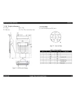
Страница 81: ... 319 x 539 x 137mm outline shown below Figure 7 2 ADF Overview Drawing 7 5 3 Interface Connector shape8 pin mini DIN male Figure 7 3 Connector Shape Table 7 2 Pin Assignment Pin No Signal I O Explanation 1 5V PWR 2 GND PWR 3 24V PWR 4 LOD IN Serial data latch 5 GND PWR 6 SO OUT Serial output data 7 SI IN Serial input data 8 SCK IN Serial clock I F ...

Страница 82: ...he reverse procedure of disassembling 7 6 1 Removal of B81334 Main Board 1 Remove the screws that are securing the Main Board Cover at the bottom and remove the Main Board Cover 2 Disconnect the six cables from the B81334 Main Board and remove the three screws gold P TITE 3 Remove the B81334 Main Board Figure 7 4 ADF Rear Screw Removal Figure 7 5 Board Removal 1 Figure 7 6 Board Removal 2 Remove t...

Страница 83: ...er and remove the Guides black Release the engagement with the internal paper guide and remove the Cover from the Case Shaft 4 Open the ASF Release Lever 5 Remove the two screws gold P TITE and two metal fittings Figure 7 7 Guide Removal Figure 7 8 Screw and Metal Fitting Removal Open Cover and remove Guides black Remove two screws and remove two metal fittings Open ...

Страница 84: ...SF Part Disassembly 1 Remove the two screws black CB flat washers at both ends of the Cover 2 Remove the two screws gold P TITE flat washers from the bottom and remove the Cover Figure 7 9 Screw Removal Figure 7 10 Screw Removal Remove two screws black screws Remove two screws ...

Страница 85: ...gure 7 11 Removal of Motor Solenoid Assembly Figure 7 12 Removal of Motor Solenoid Assembly Figure 7 13 Installed Screws and Gear C A U T I O N When removing the screws shown in Figure 7 12 be careful since the gear will pop out Remove one screw Be careful as the gear etc will pop out by removing this screw Three screws Installed on frame shaft in this order ...

Страница 86: ...iver into the gap shown below Push up the White Reference Plate forcibly in the direction of an arrow to disengage the Hook Figure 7 14 Roller Removal 1 Figure 7 15 Roller Removal 2 Figure 7 16 White Reference Plate Removal 1 Release Locks of Bushings white Remove Roller Shaft front Push up forcibly in this direction to disengage Hook White Reference Plate It is recommended to insert and push flat...

Страница 87: ...ngs When removing the screw nearest to the Lever push the Release Lever in the direction of an arrow 6 Remove the four gears One gear is secured to the PF Roller Shaft Figure 7 17 White Reference Plate Removal 2 Figure 7 18 Roller Removal Figure 7 19 Gear Removal White Reference Plate Release Bushing Locks Remove Roller Shaft rear Remove three screws Move this lever to remove this screw Remove met...

Страница 88: ...Photo Revision B APPENDIX ADF Disassembly 88 7 Remove the two screws gold P TITE and remove the black Plastic Frame Figure 7 20 Removal of Plastic Frame Remove two screws After removing screws remove this black Plastic Frame ...

Страница 89: ...e 1 After moving the Paper Edge Guide in the direction of an arrow remove the one screw silver P TITE flat washer 2 Separate the ASF Assembly and Frame Part Figure 7 21 Disassembly of ASF and Frame 1 Figure 7 22 Disassembly of ASF and Frame 2 Move Paper Edge Guide Remove screw ASF Assembly Frame Part ...

Страница 90: ...oto Revision B APPENDIX ADF Disassembly 90 3 Remove the Actuator and PE Board Assembly Figure 7 23 Removal of Actuator and PE Board Assembly 1 Figure 7 24 Removal of Actuator and PE Board Assembly 2 Actuator PE Board Assembly ...

Страница 91: ...t side ASF Feed Assembly part to the center and remove the Left ASF Feed Roller Shaft Securing Bush color white 3 Push out the ASF Feed Roller Shaft to the left and remove the ASF HP Detection Wheel from the Shaft end Figure 7 25 Removal of Right Hopper Release Lever Figure 7 26 Removal of ASF Feed Roller Securing Bush Figure 7 27 Removal of ASF HP Detection Wheel Right Hopper Release Lever ASF Fe...

Страница 92: ...opper Assembly and left and right ASF Feed Roller Assemblies 7 Slide the ASF Feed Roller Shaft to the left and remove the ASF Feed Roller Shaft from the ASF Feed Roller Shaft hole of the ASF Frame right part 8 Remove the Feed Roller Assembly from the Feed Roller Shaft Figure 7 28 ASF Hopper Assembly Removal Figure 7 29 ASF Hopper Assembly Cam Matching Position When removing the ASF Hopper Assembly...

Страница 93: ... development diagram of the ASF Assembly Figure 7 30 Disassembly of ASF Assembly Right Hopper Release Lever ASF Frame Hopper Assembly Feed Roller Assemblies Left Feed Roller Securing Bush Left Hopper Release Lever ASF HP Detection Wheel Brake Lever Torsion Spring 41 2 Feed Roller Shaft White Black ...

Страница 94: ...her parts If it has adhered wipe it completely When reinstalling the Hopper Release Levers note the assembling orientation The Feed Roller Assemblies should be set securely to the rail in the ASF Frame The left Frame part of the left Feed Roller Assembly should be set securely to the notch of the Paper Edge Guide After reinstalling the Feed Roller Securing Bush make sure that it does not come off ...

Страница 95: ... Assembly is securely locked by the Hook in the right side rear part of the ASF Frame Before reinstalling the ASF Hopper Assembly to the Feed Roller Assemblies set and temporarily secure the Compression Springs 1 66 to the Spring Mounting Hooks of the Feed Assembly After assembling move the Feed Roller Assemblies to the hole positions in the rear of the ASF Frame and release the Compression Spring...

Страница 96: ...g the ASF Hopper Assembly to the Feed Roller Assemblies set and temporarily secure the Compression Springs 1 66 to the Spring Mounting Hooks of the Feed Assembly After assembling move the Feed Roller Assemblies to the hole positions in the rear of the ASF Frame and release the Compression Springs 1 66 from the temporarily securing Hooks through the holes Do not touch the roller surface of the Feed...

Страница 97: ... Specified Grease Figure 7 38 Lubrication Points Type Name Part Number Supplier Grease G 26 1080614 EPSON Lubrication point Arms Oil type G 26 Amount of application A little Lubrication point Inner side Oil type G 26 Amount of application A little Hopper Arms ASF Frame Lubrication point Pinion Oil type G 26 Amount of application A little Lubrication point Gear teeth Oil type G 26 Amount of applica...

Страница 98: ...ion 4490 Photo Revision B APPENDIX ADF Exploded diagram 98 7 8 ADF Exploded diagram The exploded diagrams of this product are shown on the following pages B813 OPTI 1 B813 OPTI 2 B813 OPTI 3 B813 OPTI 4 B813 OPTI 5 ...

Страница 99: ...138 133 133 138 122 118 117 134 125 125 125 121 129 146 144 114 143 148 148 143 145 147 112 101 134 111 137 108 135 135 133 133 133 109 136 110 116 133 115 132 140 122 122 126 133 133 128 132 124 123 132 124 123 132 124 123 132 124 123 119 120 119 120 120 119 133 116 132 115 131 130 M L J I N N B M E ...

Страница 100: ...Automatic Document Feeder for GT X750 Perfection 4490 No 02 216 205 Rev 01 B813 OPTI 2 221 221 219 217 218 201 214 215 213 211 212 202 203 204 204 210 220 206 207 208 209 206 207 P D A B A E C ...

Страница 101: ...matic Document Feeder for GT X750 Perfection 4490 No 03 307 307 306 327 322 305 316 324 317 305 316 324 326 323 308 309 310 320 311 325 321 301 302 312 312 313 312 315 320 311 325 314 320 318 322 305 316 324 303 G F H H I K J ...

Страница 102: ...ent Feeder for GT X750 Perfection 4490 No 04 Rev 01 B813 OPTI_4 405 427 425 426 412 421 420 419 416 414 415 412 410 404 401 402 423 403 418 417 421 428 423 413 406 422 422 409 408 407 409 424 411 423 416 424 D G F L K ...

Страница 103: ...Automatic Document Feeder for GT X750 Perfection 4490 No 05 Rev 01 B813 OPTI_5 510 509 508 501 513 512 511 510 509 502 504 506 507 505 503 508 P C ...

Страница 104: ... SCREW 3X10 F ZN 134 C B P SCREW 4X12 F ZN 135 C B P TITE 3X10 F NI 136 BOARD ASSY MAIN 137 SHEET ADAPTER ASSY SUPPORT ASP UNIT 138 WIRE STOPPER 139 SHEET GUIDE B 140 GROUNDING PLATE 141 ANTI STATIC BRUSH B 142 EARTH WIRE A 143 BRACKET HINGE 144 SHEET COVER GEAR 145 GUIDE HINGE L 146 GUIDE HINGE R 147 CLIP 148 C B P TITE SCREW 3X12 F ZN 201 FRAME ASF 202 HOPPER 203 EDGE GUIDE B 204 CORK 205 LABEL ...

Страница 105: ... 408 TORSION SPRING 0 22 409 ROLLER GUIDE 410 CIRCUIT ASSY PE 411 MOUNTING PLATE REAR L 412 CLIP Table 7 4 Automatic Document Feeder Parts List Ref No Part Name 413 MOUNTING PLATE REAR R 414 ROLLER ASSY PF B 415 ROLLER ASSY EJ 416 BUSHING 6 417 LEVER RELEASE 418 TORSION SPRING 125 17 L 419 TORSION SPRING 125 17 R 420 LEVER RELEASE B 421 PLANE WASHER 4 5X0 5X8 L NA 422 C B S P2 3X6 F ZB 423 C B P T...

Отзывы: