EPSON Perfection 4490 Photo
Revision B
Disassembly / Assembly
Overview
30
4.1 Overview
This chapter explains the procedures for disassembling the major units and parts of the
product. Unless otherwise explained, reassembly should be carried out in the reverse
order of the disassembly procedure. When you have to remove any parts or
components that are not described in this chapter, refer to the exploded diagram in the
Appendix.
Before starting disassembly, always read the precautions described in the next section.
4.1.1 Precautions
Before starting the disassembly or reassembly of the product, read the following
precautions given under the headings WARNING and CAUTION.
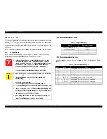
4.1.2 Recommended Tools
To protect this product from damage, use the tools indicated in the following table.
4.1.3 Recommended Screws
The following table indicates the screws used in the EPSON Perfection 4490 Photo
Scanner.
W A R N I N G
Before disassembling or reassembling this product, always
disconnect the Power Cable and Interface Cable. When you
have to work with power on for voltage measurement, etc., use
extreme care not to get an electric shock and do the work in
accordance with the procedures given in this manual.
To prevent your hands from being cut by sharp edges, always
wear gloves before starting disassembly or reassembly.
C A U T I O N
When touching any internal components, use static electricity
discharge equipment such as anti-static wrist straps.
Provide sufficient work space for disassembling and
reassembling.
Always use only the recommended tools for disassembly,
reassembly and adjustment.
Be sure to tighten the screws to the specified torque.
Use the specified grease for lubrication. Refer to Chapter 6 for
details.
Since a prototype was used to illustrate these disassembly and
assembly procedures, the appearance of some parts may differ
from those on an actual product. The procedures themselves,
however, are accurate for the retail model.
When using compressed air products; such as air duster, for
cleaning during repair and maintenance, the use of such
products containing flammable gas is prohibited.
Table 4-1. Specified Tools
Name
Epson Part Number
Phillips screwdriver, No. 2
1080532
Flat-blade screwdriver
1080527
Tweezers
1080561
Long-nose pliers
1080561
Table 4-2. Recommended Screws
No.
Name
Type
1
C.B.P. 3 x 6
Phillips Bind P-tite Screw, size M3, 8 mm length
2
C.B.P. 3 x 8
Phillips Bind P-tite Screw, size M3, 8 mm length
3
C.B.P. 3 x 12
Phillips Bind P-tite Screw, size M3, 8 mm length
4
C.P. 3 x 8
Phillips Pan Head Screw, size M3, 4 mm length
5
C.B. 3 x 3
Phillips Bind Screw, size M3, 3 mm length
6
C.B.P. 4 x 12
Phillips Bind P-tite Screw, size M3, 8 mm length
7
C.B.S. 3 x 5
Phillips Bind S-tite Screw, size M3, 5 mm length
8
C.P.F.P. 3 x 8
Phillips Pan Flange Head P-tite Screw, size M3, 8 mm length
Содержание Perfection 4490 Photo
Страница 1: ...EPSON Perfection4490Photo AutomaticDocumentFeeder Color Image Scanner Service Manual SESC05004 ...
Страница 8: ...C H A P T E R 1 PRODUCTDESCRIPTION ...
Страница 18: ...C H A P T E R 2 OPERATINGPRINCIPLES ...
Страница 25: ...C H A P T E R 3 TROUBLESHOOTING ...
Страница 29: ...C H A P T E R 4 DISASSEMBLY ASSEMBLY ...
Страница 57: ...C H A P T E R 5 ADJUSTMENT ...
Страница 59: ...C H A P T E R 6 MAINTENANCE ...
Страница 63: ...C H A P T E R 7 APPENDIX ...
Страница 66: ...Model GT X750 Perfection 4490 Photo Board Main Board Rev A Sheet 1 1 ...
Страница 68: ...Model GT X750 Perfection 4490 Photo Board DRV Board Assy Rev A Sheet 1 1 ...
Страница 69: ...Model GT X750 Perfection 4490 Photo Board Image Sensor Board Rev B Sheet 1 1 ...
Страница 70: ...Model GT X750 Perfection 4490 Photo Board SUB Board Rev A Sheet 1 1 ...
Страница 71: ...Model GT X750 Perfection 4490 Photo Board SUB C Board Rev A Sheet 1 1 ...
Страница 72: ...Model GT X750 Perfection 4490 Photo Board SUB D Board Rev A Sheet 1 1 ...
Страница 74: ...GT X750 Perfection 4490 Photo NO 1 Rev 02 B176 ACCE 0012 10 20 30 40 400 401 ...
Страница 76: ...R ev 01 B176 CAS E 002 GT X750 Perfection 4490 Photo NO 3 110 111 101 102 ...

