
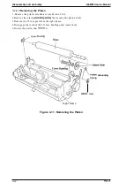
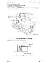
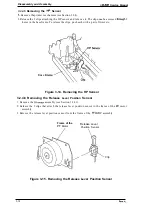
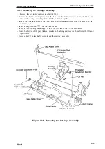

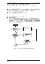


Adjustments
Service Manual
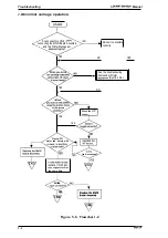
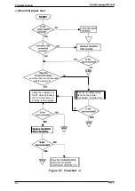
4.2.2
Bidirectional Adjustment
This
section describes the adjustment procedure necessary when the
printer is reassembled
or when parts are reinstalled or replaced. This procedure is also necessary if the main board
assembly has been replaced.
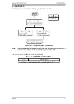
Notes:
●
the
rep/aced, perform the Defaults& Machine Information Settings
procedure first, then perform
Adjustment procedure.
●
installed
the
. Do
the
Adjustment procedure the input voltage is fluctuating heavily.
. The optional color upgrade
removed when
the
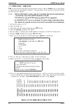
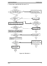
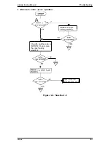
1. Connect the printer to a PC.
2. Turn the printer on.
3. Load paper into the pninterbypressing the
button.
4. Load the
program onto the PC.
5. Insert a diskette containing the LQ-300Adjustment Program into the PC’s diskette drive.
6. Load the
Adjustment Program’’BKMENU.BAS”.
7. When you run the program, the following message
on the display:
Adjustment Program
1.
A), EIS, EIB, EUL,
EHK
2. EDG, EFS
3. EDG
4. El-r
5. END
Do nut input unspecified destination!
Please input each destination
1-4 ) and Enter Key.
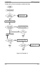
8.
Press 1-4, then go to adjustment program of each destination
9.
When you input -4, the following message
on the display:
Adjustment Program
1.
Adjustment
2. Defaults& Machine Information Settings
3. END
If ready, press 1-3 and the
Enter key. –
10. Type 1 to select
Adjustment then press Enter.
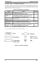
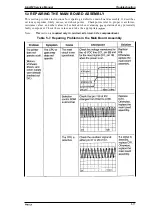
5 rows of H characters in both draft and LQ modes.
After 10 line feeds, the printer prints
When the printer begins bidirectional
printing, the message
appears on the
-
LQ
Figure 4-2. The Bidirectional Pattern Print
4-4
Содержание LQ-300 - Impact Printer
Страница 1: ...EPSON TERMINAL PRINTER LQ 300 SERVICE MANUAL EPSON ...
Страница 5: ...REVISION SHEET Revision Issue Date Revision Page Rev A September 28 1994 1st issue f v 1 ...
Страница 34: ...c f ...
Страница 101: ...Maintenance LQ 300 Service Manual Figure 6 1 LQ 300 Lubrication Points 6 2 Rev A ...
Страница 108: ...Appendix LQ 300 Service Manual I I I J a 1 e 1 1 l il G I Figure A 4 C130 PSE Circuit Diagram A 8 Rev A ...
Страница 110: ... Figure A 6 C130 PSB PSE Component Layout ...
Страница 111: ...Lq 3OO Service Manual Appendix A 4 EXPLODED DIAGRAMS Figure A 7 LQ 300 Exploded Diagram 1 Rev A A 1 1 ...
Страница 112: ...Appendix LC MMS vbeMantd Q ix iyii t v Figure A 8 LQ 300 Exploded Diagram 2 A 12 Rev A ...
Страница 113: ...L WOO Service Manual Appendix U3 o b o r I I 4 o u o b f Figure A 9 Color Upgrade Kit Exploded Diagram Rev A A 13 ...
Страница 119: ... f ...


