


Operating Principles
Service Manual
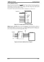
2.3.8 Paper
Feed Motor Driver Circuit
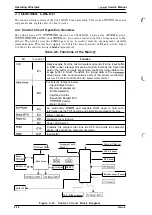
Figure 2-19 shows the paper feed motor driver circuit, an open-loop, constant-voltage drive with
1-2 phase excitation.
The ports (pins 7-lo) on the CPU are used to control the stepping motor. The pulse signal from the
controls four
and the stepping motor. The motor is driven at six speeds, 300,500,
600, 1000, 1200, and 1300 pps, to correspond to the idling voltage, the paper handling condition,
and the volume of paper feeding.
CPU controls motor driving speed. At the holding time, the
voltage is changed VX
V) into VL (+5 V) via
Q6 by the gate array.
Gate
Array
143
I
CPU (ICI)
M l l
MIO
PF Motor Drive
Transistors
PF_A
P FA
‘
VL
Vx
Figure 2-19. Paper Feed Motor Driver Circuit Diagram
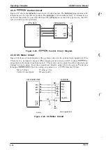
2.3.9
Driver Circuit
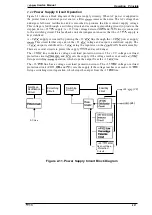
Figure 2-20 shows the
driver circuit block diagram. Print data, already expanded into
image
is split by the
and transferred to the
circuit in the gate array in the system.
Port
(pin 66) of
samples
voltage of the +35
via the A/D converter. By
sampling the +35
line voltage and deterrninin g the length of the head drive signal, it is
possible to maintain the energy supplied to
head at a constant level. If the voltage from the
+35 V line is HIGH,
shortens
output
If the voltage from
+35
line is LOW,
ICI lengthens the output pulse.
CPU
BUS
62
Gate Array
VP
QM1 -6
●
,
●
●
●
●
●
●
●
●
●
:
●
●
●
●
●
●
●
,
●
+5
VP
d
Figure 2-20.
Driver Circuit Diagram
#24
2-16
Содержание LQ-300 - Impact Printer
Страница 1: ...EPSON TERMINAL PRINTER LQ 300 SERVICE MANUAL EPSON ...
Страница 5: ...REVISION SHEET Revision Issue Date Revision Page Rev A September 28 1994 1st issue f v 1 ...
Страница 34: ...c f ...
Страница 101: ...Maintenance LQ 300 Service Manual Figure 6 1 LQ 300 Lubrication Points 6 2 Rev A ...
Страница 108: ...Appendix LQ 300 Service Manual I I I J a 1 e 1 1 l il G I Figure A 4 C130 PSE Circuit Diagram A 8 Rev A ...
Страница 110: ... Figure A 6 C130 PSB PSE Component Layout ...
Страница 111: ...Lq 3OO Service Manual Appendix A 4 EXPLODED DIAGRAMS Figure A 7 LQ 300 Exploded Diagram 1 Rev A A 1 1 ...
Страница 112: ...Appendix LC MMS vbeMantd Q ix iyii t v Figure A 8 LQ 300 Exploded Diagram 2 A 12 Rev A ...
Страница 113: ...L WOO Service Manual Appendix U3 o b o r I I 4 o u o b f Figure A 9 Color Upgrade Kit Exploded Diagram Rev A A 13 ...
Страница 119: ... f ...


