


Service Manual
Operating Principle
2.2.2
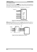
Power Supply Circuit Operation
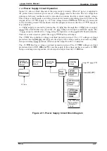
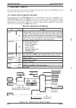
Figure 2-11 shows a block diagram of the power supply circuitry. When AC power is supplied to
the printer from an external power source, a filter
removes the noise. The AC voltage then
undergoes full-wave rectification and is smoothed to produce the direct current supply voltage.
This voltage is fed through a switching circuit and secondary smoothing circuit to produce the
stepped down +35
supply. A +35 V line voltage detector
and
circuit is connected
to the switching circuit. This feedback control arrangement ensures that the +35
supply is
kept stabilized.
A +9
supply is created by putting the +35
line through the +9
power supply
This circuit further steps down the +35
voltage and outputs a stabilized supply. The
+9
output is stabilized to +5
using the regulator on the
MAIN board assembly.
There are several circuits to protect the supply
and avoid danger.
The +9
line contains a voltage overload protection circuit. The +9 V voltage overload
protection circuit
and
cuts the supply if the voltage reaches or exceeds
It stops switching
operation, which stops the output from the +35
line.
The +35
line has a voltage overload protection circuit. The +35
voltage overload
protection circuit ( ZD52,
and
) cuts the supply if the voltage reaches or e36
It stops switching circuit operation, which stops the output from the +35
line.
Full-Wave
Rectification —
Smoothing
Switching
Smoothing
Circuit
Circuit
Circuit
Circuit
Filter Circuit
AC Line
+9
Line
Over-voltage
Protection
Circuit
+35
I
— Over-voltage
Protection
Figure 2-11. Power Supply Circuit
Circuit
Block Diagram
+35
(VP)
(VL)
2-11
Содержание LQ-300 - Impact Printer
Страница 1: ...EPSON TERMINAL PRINTER LQ 300 SERVICE MANUAL EPSON ...
Страница 5: ...REVISION SHEET Revision Issue Date Revision Page Rev A September 28 1994 1st issue f v 1 ...
Страница 34: ...c f ...
Страница 101: ...Maintenance LQ 300 Service Manual Figure 6 1 LQ 300 Lubrication Points 6 2 Rev A ...
Страница 108: ...Appendix LQ 300 Service Manual I I I J a 1 e 1 1 l il G I Figure A 4 C130 PSE Circuit Diagram A 8 Rev A ...
Страница 110: ... Figure A 6 C130 PSB PSE Component Layout ...
Страница 111: ...Lq 3OO Service Manual Appendix A 4 EXPLODED DIAGRAMS Figure A 7 LQ 300 Exploded Diagram 1 Rev A A 1 1 ...
Страница 112: ...Appendix LC MMS vbeMantd Q ix iyii t v Figure A 8 LQ 300 Exploded Diagram 2 A 12 Rev A ...
Страница 113: ...L WOO Service Manual Appendix U3 o b o r I I 4 o u o b f Figure A 9 Color Upgrade Kit Exploded Diagram Rev A A 13 ...
Страница 119: ... f ...


