


Operating Principles
Service Manual
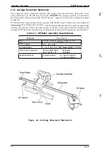
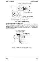
2.1.2 Carriage Movement Mechanism
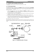
The carriage movement mechanism consists of the carnage assembly, CR motor, timing belt, driven
pulley, HP sensor, etc. The CR motor drives the
The carnage assembly is connected to
the timing belt, which is moved by the CR motor.
Figure 2-2 shows the carriage movement
mechanism.
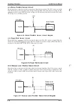
The printer detects
carriage home position with the HI? sensor. This sensor is the basis for
the carriage home position. The HP sensor informs the CPU of the carriage home
position. The sensor is ON, when the carriage is pushed to the right or left. The striker on the
carriage
the sensor to indicate the carriage home position, which toggles the sensor to OFF.
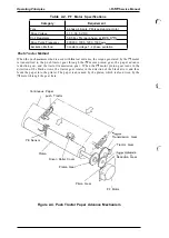
Table 2-1. CR Motor Assembly Specifications
I
Category
I
Requirement
Type
4-phase, 96-pole,
stepping motor
Drive
31.5 -38.5 VDC
Coil Resistance
I
1 9 . 6
8 %
Drive Pulse Frequency
Normal Mode Draft
2400
Color Mode LQ
1600
DDS
I
Excitation Method
Constant-voltage
2-2 phase excitation
1-2 phase excitation
Figure 2-2. Carriage Movement Mechanism
2-2
Содержание LQ-300 - Impact Printer
Страница 1: ...EPSON TERMINAL PRINTER LQ 300 SERVICE MANUAL EPSON ...
Страница 5: ...REVISION SHEET Revision Issue Date Revision Page Rev A September 28 1994 1st issue f v 1 ...
Страница 34: ...c f ...
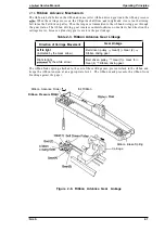
Страница 101: ...Maintenance LQ 300 Service Manual Figure 6 1 LQ 300 Lubrication Points 6 2 Rev A ...
Страница 108: ...Appendix LQ 300 Service Manual I I I J a 1 e 1 1 l il G I Figure A 4 C130 PSE Circuit Diagram A 8 Rev A ...
Страница 110: ... Figure A 6 C130 PSB PSE Component Layout ...
Страница 111: ...Lq 3OO Service Manual Appendix A 4 EXPLODED DIAGRAMS Figure A 7 LQ 300 Exploded Diagram 1 Rev A A 1 1 ...
Страница 112: ...Appendix LC MMS vbeMantd Q ix iyii t v Figure A 8 LQ 300 Exploded Diagram 2 A 12 Rev A ...
Страница 113: ...L WOO Service Manual Appendix U3 o b o r I I 4 o u o b f Figure A 9 Color Upgrade Kit Exploded Diagram Rev A A 13 ...
Страница 119: ... f ...


