

Maintenance 8. Arm #4
G10 / G20 Rev.20
173
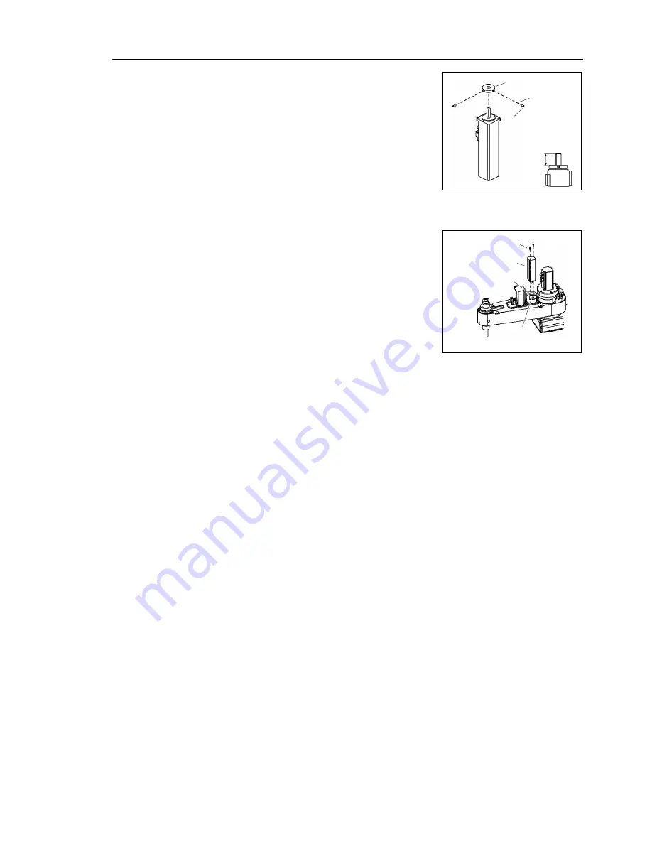
Joint #4 motor
Installation: G20
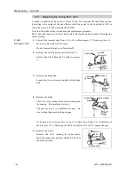
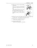
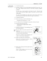
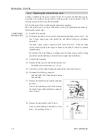
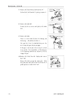
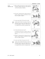
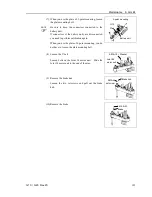
(1) Mount the ring to the Joint #4 motor.
Be sure to fit the end face of the ring 16.5 mm
from the end face of the motor shaft.
Tighten one of the set screws on the flat face of the
motor shaft until the screw just touches the
surface.
Insert a bushing into the other set screw hole to
prevent damage to the motor shaft. Then, tighten
both set screws.
Bushing
Ring
2-M3
×
8
set screw
16.5 mm
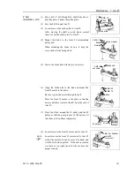
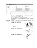
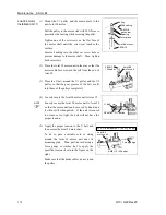
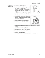
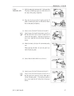
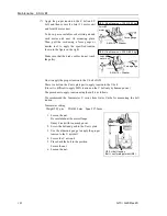
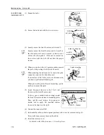
(2) Secure the Joint #4 motor to the reduction gear
unit so that the Joint #4 motor cable faces toward
the left from the end of Arm #2.
2-M4
×
10
Joint #4 motor
Reduction
gear unit
M3
×
10
(Securing the motor shaft)
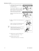
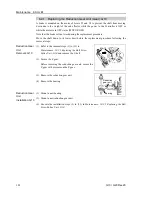
(3) Secure the motor shaft to the reduction gear unit.
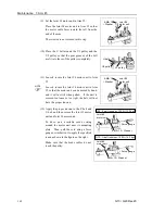
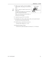
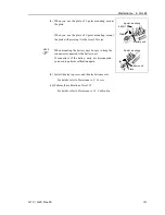
(4) Connect the connectors X241, X41, and X64.
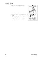
(6) Re-bundle the cables in their original positions with a wire tie removed in the removal
procedure.
Do not allow unnecessary strain on the cables.
(7) Install the arm top cover and the arm bottom cover.
For details, refer to
Maintenance: 3. Covers
.
(8) Perform the calibration of Joint #4.
For details on the calibration method, refer to
Maintenance: 14. Calibration
.
Содержание G10 Series
Страница 1: ...Rev 20 EM183R3619F SCARA ROBOT G10 G20 series MANIPULATOR MANUAL ...
Страница 2: ...MANIPULATOR MANUAL G10 G20 series Rev 20 ...
Страница 8: ...vi G10 G20 Rev 20 ...
Страница 14: ......
Страница 102: ...Setup Operation 5 Motion Range 90 G10 G20 Rev 20 ...
Страница 103: ...Maintenance This volume contains maintenance procedures with safety precautions for G10 G20 series Manipulators ...
Страница 104: ......