E
E
p
p
s
s
o
o
n
n
E
E
T
T
-
-
4
4
5
5
5
5
0
0
,
,
L
L
6
6
5
5
5
5
/
/
6
6
5
5
6
6
R
R
e
e
v
v
i
i
s
s
i
i
o
o
n
n
B
B
D
D
i
i
s
s
a
a
s
s
s
s
e
e
m
m
b
b
l
l
y
y
/
/
R
R
e
e
a
a
s
s
s
s
e
e
m
m
b
b
l
l
y
y
D
D
e
e
t
t
a
a
i
i
l
l
e
e
d
d
D
D
i
i
s
s
a
a
s
s
s
s
e
e
m
m
b
b
l
l
y
y
/
/
R
R
e
e
a
a
s
s
s
s
e
e
m
m
b
b
l
l
y
y
P
P
r
r
o
o
c
c
e
e
d
d
u
u
r
r
e
e
f
f
o
o
r
r
e
e
a
a
c
c
h
h
P
P
a
a
r
r
t
t
/
/
U
U
n
n
i
i
t
t
4
4
6
6
Confidential
Confidential
Scanner Housing Lower Assy
Scanner Housing Lower Assy
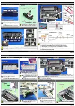
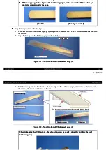
Install the Scanner driver gears, scanner drive lever, and Extension Spring 0.526 as shown above.
Install the Scanner driver gears, scanner drive lever, and Extension Spring 0.526 as shown above.
ScannerS drive gears
ScannerS drive gears
Extension Spring 0.526
Extension Spring 0.526
Scanner drive lever
Scanner drive lever
Scanner Housing Lower Assy
Scanner Housing Lower Assy
Panel Unit
Panel Unit
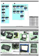
Remove the Panel Unit as follows.
Remove the Panel Unit as follows.
1.
1. Remove t
Remove the screw
he screws (x 2) t
s (x 2) that secur
hat secure the Pan
e the Panel Unit.
el Unit.
2.
2. Release th
Release the hooks (x 3) o
e hooks (x 3) on the Panel Un
n the Panel Unit, and detac
it, and detach the Panel Un
h the Panel Unit.
it.
3.
3. Disconn
Disconnect the Panel FFC and the Speaker cable from the conne
ect the Panel FFC and the Speaker cable from the connectors on the backface of the Panel Board
ctors on the backface of the Panel Board, and remove the Panel Unit.
, and remove the Panel Unit.
Panel Unit (Backface)
Panel Unit (Backface)
Panel Unit
Panel Unit
C.B.P-TITE SCREW 3x10 F/ZB-3C (6 ± 1
C.B.P-TITE SCREW 3x10 F/ZB-3C (6 ± 1
kgf
kgf
··
cm)
cm)
Hook
Hook
Step3
Step3
P
Pa
an
neel B
l Bo
oa
arrd
d
S
Sp
peea
ak
keer c
r ca
ab
bllee
Panel FFC
Panel FFC
Panel Board
Panel Board
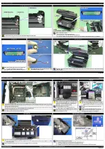
When reassembling, align the dowels on the Panel Housing
When reassembling, align the dowels on the Panel Housing
Assy with the positioning holes on the Panel Board.
Assy with the positioning holes on the Panel Board.
Tighten the screws in the order indicated in the figure above.
Tighten the screws in the order indicated in the figure above.
C.B.P-TITE SCREW 3x10 F/ZN-3C (6
C.B.P-TITE SCREW 3x10 F/ZN-3C (6
±
±
1kgf
1kgf
··
cm)
cm)
Dowel and positioning hole
Dowel and positioning hole
P
Pa
an
neel
l H
Ho
ou
ussiin
ng
g A
Assssy
y
P
Pa
an
neel
l B
Bo
oa
arrd
d
1
1
2
2
3
3
4
4
Speaker
Speaker
When handling the Speaker, do not pinch the middle of the woofer
When handling the Speaker, do not pinch the middle of the woofer
cone but make sure to hold it by the rim.
cone but make sure to hold it by the rim.
Speaker
Speaker
OK
OK
NG
NG
Speaker
Speaker
Housing Upper
Housing Upper
Since the Housing Upper is secured by the hooks (x 2) shown above, release the hooks with a precision screwdriver or a similar tool when removing
Since the Housing Upper is secured by the hooks (x 2) shown above, release the hooks with a precision screwdriver or a similar tool when removing
the Housing Upper.
the Housing Upper.
Housing Upper
Housing Upper
Left
Left
Hook
Hook
Precision driver
Precision driver
Right
Right
Precision driver
Precision driver
Hook
Hook
Содержание ET-4550
Страница 9: ...Confidential Confidential CHAPTER CHAPTER 1 1 TROUBLESHOOTING TROUBLESHOOTING ...
Страница 39: ......
Страница 46: ...Confidential Confidential Confidential Confidential CHAPTER CHAPTER 3 3 ADJUSTMENT ADJUSTMENT ...
Страница 48: ......

