5. End Effectors
Part 1: Setup & Operation
26
If you move the manipulator horizontally when the position of Joint #3 is low, it may cause
over shoot at the time of final positioning. We recommend that the height of the Joint #3
be as high as possible when you move the manipulator horizontally.
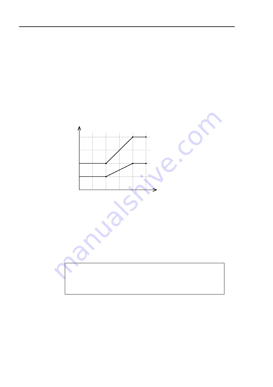
Moment of inertia and the ACCEL setting
When dealing with rotating shafts, you must account for the moment of inertia of a load.
There are also ratings and maximum values for allowable moments of inertia. They differ
depending on the Weight setting described above. The ratings and maximum moments of
inertia are as follows:
W : Weight setting (kg)
I : Allowable moment of inertia (kg
⋅
m
2
)
0.03
0.02
0.01
0.04
I (kg
⋅
m
2
)
W (kg)
0
0
1
2
3
4
5
Rated allowable
moment of inertia
Maximum allowable
moment of inertia
Figure 14. Allowable moment of inertia
When the moment of inertia of the end effector is equal to or less than the rated allowable
moment of inertia, you may operate the robot at the maximum acceleration/deceleration speed
setting (ACCEL 100, 100).
When the rated allowable moment of inertia is exceeded, lower the acceleration/ deceleration
speed using the ACCEL command. Using the results of the following formula as a guideline,
input the suitable value for the given conditions.
A = I
0
/ I
×
100 (%)
A : ACCEL value in accordance with the moment of inertia
I
0
: Rated allowable moment of inertia
I : Moment of inertia of the end effector
<Example> For the end effector weighting 3kg and with a moment of inertia of 0.02kg
⋅
m
2
WEIGHT 3
A = 0.015 / 0.02
×
100 = 75%
ACCEL 75,75
Содержание EL Series
Страница 1: ...ES EL series Rev 9 EM019R893F SCARA ROBOT MANIPULATOR MANUAL ...
Страница 2: ...MANIPULATOR MANUAL ES EL series Rev 9 ...
Страница 12: ...x ...
Страница 14: ...2 ...
Страница 16: ...1 Manipulator Part Names Part 1 Setup Operation 4 ...
Страница 30: ...4 User Wires and Pneumatic Tubes Part 1 Setup Operation 18 ...
Страница 42: ...5 End Effectors Part 1 Setup Operation 30 ...
Страница 44: ...6 Attaching a Camera Valve and Other Devices Part 1 Setup Operation 32 ...
Страница 68: ...8 Motion Range and Robot Coordinates Part 1 Setup Operation 56 ...
Страница 70: ...9 Emergency Stop Part 1 Setup Operation 58 ...
Страница 80: ...11 Clean Model Part 1 Setup Operation 68 ...
Страница 92: ...80 ...
Страница 94: ...Maintenance Safety Precautions Part 2 Maintenance 82 ...
Страница 104: ...2 Opening the Covers Part 2 Maintenance 92 ...
Страница 112: ...3 Replacing the Cable Unit Part 2 Maintenance 100 ...
Страница 138: ...5 Replacing the Motors Part 2 Maintenance 126 ...
Страница 162: ...6 Replacing the Reduction Gear Units Part 2 Maintenance 150 ...
Страница 186: ...9 Replacing the Ball Screw Spline Unit Part 2 Maintenance 174 ...
Страница 210: ...11 Calibration Part 2 Maintenance 198 ...
Страница 214: ...12 Clean Model Maintenance Part 2 Maintenance 202 ...
Страница 224: ...13 Protected Model Maintenance Part 2 Maintenance 212 13 6 Wiring Schematic 2 ...
Страница 236: ...14 Maintenance Part Lists Part 2 Maintenance 224 ...


