Operating Principles
2.2.1.5
Parallel Interface Circuit
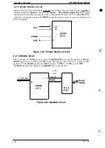
Figure 2-41 shows the parallel interface circuit block diagram. Data sent from the host
is
latched within the
by the STROBE
signal.
The
outputs the
BUSY signal
automatically to stop the host computer from sending additional data. The CPU
resets the
BUSY
signal after reading the data from the
so that the printer is ready to receive more data from
the host computer.
——————b
Latch
1-” ”-:
Figure 2-41. Parallel Interface Circuit
2.2.1.6
Circuit
This circuit uses the
receiver/driver
to change the signal level
the
signal level (-12
or
to the
signal level (O V or +5 V) or from the
signal level to the
signal level.
co5
to +12
and –12
The
standard cell changes serial
data to parallel data.
serial
Data
Transmit
Parallel Data
-.................. ------”--”-b
MA)(2O2
Figure 2-42.
Circuit
.-., ..,
.
-’
2-28
Rev.
Содержание C11C605001 - DFX 9000 B/W Dot-matrix Printer
Страница 1: ...EPSON TERMINAL PRINTER EPL 9000 SERVICE MANUAL EPSON ...
Страница 8: ...REVISION SHEET Revision Isaue Date Rev A I Augusl 5 1994 Revision Page I 1s issue I c c vii ...
Страница 117: ...Disassembly and Assemb y EPL UXM Service MAnual I T I Figure 3 50 Removing the ROS Unit 3 32 Rev A ...
Страница 118: ...Chapter 4 Adjustments No Adjustment is required in this product ...
Страница 161: ...EPSON ...


