Service Manual
Disassembly and Assembly
3.2.4.10
Sensor Removal
1.
Remove the top cover. (Refer to Section 3.2.1.2.)
2. Remove the left cover. (Refer to Section
3 Remove the
(Refer to Section 3.2.4.4.)
4. Remove the trans. chute assembly. (Refer to Section 3.2.4.7.)
5. Remove the link assembly. (Refer to Section
6.
5
screws
x 8) securing the front frame assembly to the front cover.
7. Remove
screw
x 8) securing the
sensor, and remove it.
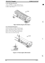
8. Discomect connector
from the
sensor.
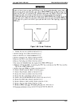
Figure 3-33. Removing
the
Sensor
3.2.4.11 Bottom Plate Removal
1.
2.
3
4.
5.
6.
7.
8.
Remove the top cover. (Refer to Section 3.2.1.2.)
Remove the left cover. (Refer to Section 3.2.1.3.)
Remove the BTR assembly. (Refer to Section 3.2.4.4.)
Remove the trans. chute assembly. (Refer to Section 3.2.4.7.)
Remove the link assembly. (Refer to Section 3.2.4.1.)
Remove 5
screws
x 8) securing the front frame assembly to the front cover.
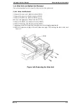
Remove 2 springs from the bottom plate.
Remove
screw
x 6) securing the support bracket, and remove the bottom plate after
removing the support bracket.
Figure 3-34. Removing the
Bottom Plate
Rev.
3-21
Содержание C11C605001 - DFX 9000 B/W Dot-matrix Printer
Страница 1: ...EPSON TERMINAL PRINTER EPL 9000 SERVICE MANUAL EPSON ...
Страница 8: ...REVISION SHEET Revision Isaue Date Rev A I Augusl 5 1994 Revision Page I 1s issue I c c vii ...
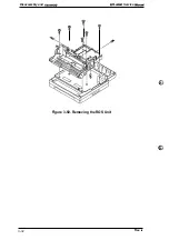
Страница 117: ...Disassembly and Assemb y EPL UXM Service MAnual I T I Figure 3 50 Removing the ROS Unit 3 32 Rev A ...
Страница 118: ...Chapter 4 Adjustments No Adjustment is required in this product ...
Страница 161: ...EPSON ...


