Page 52
EPS Stromversorgung GmbH
Alter Postweg 101 • 86159 Augsburg
Germany
ELR 9000 Series
Fon: +49 821 / 570451-0
Fax: +49 821 / 570451-25
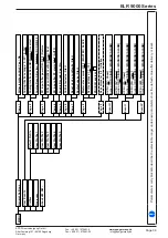
3.5.4.4 Overview of the Sub-D Socket
3.5.4.5
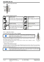
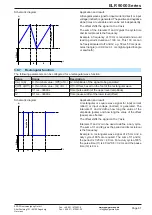
Simplified diagram of the pins
+
Digital Input (DI)
It requires to use a switch with low resist-
ance (relay, switch, circuit breaker etc.) in
order to send a clean signal to the DGND.
V~0.5
AGND
Analog Input (AI)
High resistance input (impedance
>40 k....100 kΩ) for an OA circuit.
4.
7k
12V
+10V
Digital Output (DO)
A quasi open collector, realised as high
resistance pull-up against the internal sup-
ply. In condition LOW it can carry no load,
merely switch, as shown in the diagram
with a relay as example.
V~2
AGND
Analog Output (AO)
Output from an OA circuit, only mini-
mally impedant. See specifications
table above.
3.5.4.6 Application examples
a) Switching off the DC input via the pin “REM-SB”
A digital output, e.g. from a PLC, may be unable to cleanly effect this as it may
not be of low enough resistance. Check the specification of the controlling ap
-
plication. Also see pin diagrams above.
In remote control, pin REM-SB is be used to switch the DC input of the device on and off. This is
also available without remote control being active.
It is recommended that a low resistance contact such as a switch, relay or transistor is used to
switch the pin to ground (DGND).
Following situations can occur:
• Remote control has been activated
During remote control via analog interface, only pin “REM-SB” determines the states of the DC input, according to
the levels definitions in
. The logical function and the default levels can be inverted by a parameter in the
setup menu of the device. See
.
If the pin is unconnected or the connected contact is open, the pin will be HIGH. With parameter
“Analog interface REM-SB” being set to “normal”, it requests “DC input on”. So when activating
remote control, the DC input would instantly switch on.

