22
EN
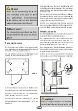
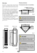
First make a rectangular cut-out in the cabin wall
as shown in the Fig. 5.
For the foot-zone radiator the cut-out should
be horizontal.
The wall above the radiator should be hollow
inside to let the hot air rise.
Draw the connection cable from the radiator up
to the ceiling through the duct in the cabin wall.
Then insert the radiator into the prepared wall
aperture and secure it with the mounting screws.
Pay attention that the cable connection of the
radiator must be oriented downwards unless
others is specified by the cabin manufacturer.
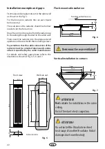
For details and safety gaps please refer to the
illustrations shown in Fig. 4, 5, 6 and 7.
Installation example and gaps:
Flush-mounted installation
Fig. 6
Vertical installation in corners
Fig. 7
!
Device must be rear-ventilated!
!
ATTENTION!
Do not install the IR radiator in direct
heat range of another IR radiator. Risk of
damages due to overheating!
Front view
Wall cut-out
950
~200
940
178
167
693
~60
Fig. 5
!
ATTENTION!
Not
suitable for installation in the cabin
ceiling.
Risk of fire due to heat congestion.
Holzschutz
40 mm
164 mm
178 mm
17 mm
~60 mm
90°
164 mm
178 mm
17 mm
~60 mm
Dimensions in mm
Protective guard rail if necessary
Содержание VITAE
Страница 2: ...2 Deutsch 3 English 15 27...
Страница 27: ...27 RU 28 30 31 32 32 35 33 33 34 35 36 36 37 38 ASB 38...
Страница 28: ...28 RU...
Страница 29: ...29 RU 8 230V50Hz EU 60335 2 53 VDE 0700 53...
Страница 30: ...30 RU 3 5...
Страница 32: ...32 RU 1 3 5 2 4 7 9 6 8 5 9 94 4396 94 2046 2 2b 3 5 1 3500 750 4 9 3 5 3b 2 2b 2 5 944396 944960 942046 3500...
Страница 33: ...33 RU 3 3 750 50 350 500 15 4 94 4954 9 min 50 cm min 7 cm IR Emitter Vitae min 15 cm min 9 cm 7 50 9 4 4 6...
Страница 35: ...35 RU 8 3 8 N PE L 1 N PE L 9 10 2 11 3 2 12 11...
Страница 36: ...36 RU 5 4...
Страница 38: ...38 RU ASB I II III IV V VI 24 06 2015...


