


Installing the Switch on a Flat Surface
3-8 Hardware Installation
Guidelines for Flat Surface Installation
Locate
the
switch
within
152
cm
(5
ft)
of
its
power
source
and
on
a
surface
as
shown
in
Figure 3
‐
4
.
If
an
optional
redundant
power
system
is
going
to
be
installed
and
connected
to
the
14
‐
pin
Redundant
Power
Supply
input
connector
on
the
rear
of
the
switch,
refer
to
the
installation
guide
shipped
with
the
redundant
power
system.
If
you
are
installing
several
switches
in
a
stack,
proceed
to
“
Connecting
High
‐
Speed
Stacking
Cables
”
on
page 3
‐
11.
If
the
switch
is
being
installed
as
a
standalone
switch,
proceed
to
“
Connecting
AC
and
PoE
Power
”
on
page 3
‐
15
for
power
connection
instructions.
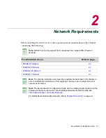
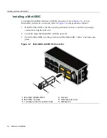
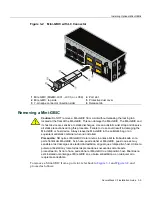
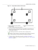
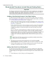
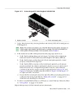
Figure 3-4 Area Guidelines for Switch Installation on Flat Surface
Caution:
To ensure proper ventilation and prevent overheating, leave a minimum
clearance space of 5.1 cm (2.0 in.) at the left, right, and rear of the switch.
Do not connect the switch to the primary power source until instructed to do so later in the
installation process.
Precaución:
Para asegurar una buena ventilación y evitar que el sistema se
sobrecaliente, deje un espacio mínimo de 5.1 cm (2 pulgadas) con respecto a los lados y
a la parte posterior del aparato.
No conecte el dipositivo a la fuente primaria hasta que no se le indique.
1
Approximately 152 cm (5 ft) from power source
3
44.5 cm (17.52 in.) for proper ventilation
2
4.45 cm (1.75 in.) per switch. (Vertical clearance
depends on number of switches stacked.)
4
41.9 cm (16.5 in.) for proper ventilation
Содержание SecureStack B3G124-24P
Страница 2: ......
Страница 14: ...xii...
Страница 68: ...Using the Reset Switch 4 10 Troubleshooting...
Страница 76: ...Regulatory Compliance A 8 Specifications...


