


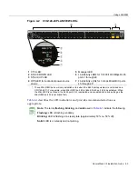


Connecting to the Network
3-22 Hardware Installation
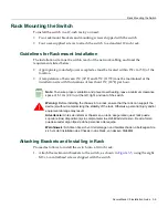
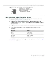
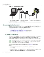
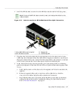
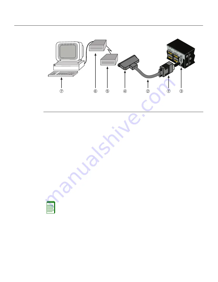
Figure 3-12 Connecting to a Modem
Connecting to the Network
The
following
procedures
cover
the
cable
connections
from
the
network
or
other
devices
to
the
switch
RJ45
ports
or
any
installed
optional
Mini
‐
GBIC.
•
Connecting
UTP
Cables
on
page 3
‐
22
•
Connecting
Fiber
‐
Optic
Cables
to
MT
‐
RJ
Ports
on
page 3
‐
26
•
Connecting
Fiber
‐
Optic
Cables
to
LC
Ports
on
page 3
‐
28
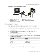
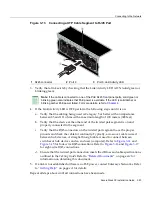
Connecting UTP Cables
The
fixed
RJ45
front
panel
ports
are
10/100/1000
Mbps
ports
and
have
internal
crossovers.
When
connecting
a
workstation
to
these
ports,
use
a
straight
‐
through
cable.
When
connecting
networking
devices
to
these
ports,
such
as
a
bridge,
repeater,
or
router,
use
a
crossover
cable.
To
connect
twisted
pair
segments
to
the
switch,
refer
to
Figure 3
‐
13
and
proceed
as
follows:
1.
Ensure
that
the
device
to
be
connected
at
the
other
end
of
the
segment
is
powered ON.
2.
Connect
the
twisted
pair
segment
to
the
switch
by
inserting
the
RJ45
connector
on
the
twisted
pair
segment
into
the
desired
RJ45
port
(for
example,
Port
8).
1
DB9 female cable connector
4
DB25 male connector
7
PC with VT emulation application
2
Serial interface cable
5
Local modem
3
DB9 male Console port
6
Remote modem
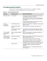
Note:
All fixed RJ45 front panel ports support Category 5 Unshielded Twisted Pair (UTP)
cabling with an impedance between 85 and 111 ohms. Category 3 cable may be used if
the connection is going to be used only for 10 Mbps.
Содержание SecureStack B3G124-24P
Страница 2: ......
Страница 14: ...xii...
Страница 68: ...Using the Reset Switch 4 10 Troubleshooting...
Страница 76: ...Regulatory Compliance A 8 Specifications...


