Quad User Modules
User Manual
80-14001000-03
2–16
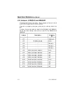
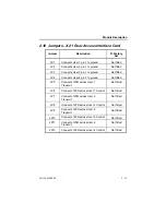
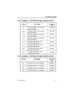
2.14 Jumpers - V.24 & V.35 Rear Backup Interface
Card
Jumper
Description
F=Factory
Set
JP1
Connects User 1-4 pin 1 and also Link
1-4 pin 1 to ground
Not fitted
2.15 DIL Switches
There is an 8 way DIL switch on the front pcb.
Pole 1 is reserved for internal use.
Pole 3 performs a factory default when it is ON. Having defaulted the
card, pole 3 must then be turned OFF to enable the card to operate. The
card can also be factory defaulted by holding in a front panel button
while inserting it into the shelf. Always check that a factory default has
been successful by examining the store locations that were known to be
set.
All other DIL switches are unused.
Содержание SBUQHS/QHB
Страница 91: ...Quad User Modules User Manual 80 14001000 03 12 2 12 1 SBUQLS 12 1 1 SBUQLS QHB Configuration Menu...
Страница 92: ...Menu Diagrams 80 14001000 03 12 3...
Страница 93: ...Quad User Modules User Manual 80 14001000 03 12 4 12 1 2 SBUQLS QLB Operation Menu...
Страница 94: ...Menu Diagrams 80 14001000 03 12 5 12 2 SBUQHS 12 2 1 SBUQHS QHB Operation Menu...
Страница 95: ...Quad User Modules User Manual 80 14001000 03 12 6 12 2 2 SBUQHS QHB Configuration Menu...
Страница 96: ...Menu Diagrams 80 14001000 03 12 7...

