


Memory Locations and Replacement Procedures
B-6 Mode Switch Bank Settings and Optional Installations
)
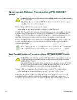
2.
Refer
to
Figure B
‐
2
.
Push
the
connector
arms
away
from
the
DIMM
and
simultaneously
lift
the
DIMM
enough
to
release
it
from
the
connector
fingers.
3.
Rotate
the
DIMM
upwards,
then
remove
it
from
the
connector
fingers.
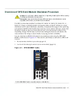
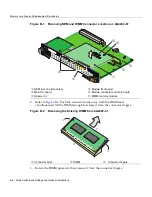
Figure B-1 Removing NEM and DIMM Connector Location on 4G4282-41
➀
NEM (not on all modules)
➃
Module front panel
➁
Main PC board
➄
Module connectors on main board
➂
Screws (3)
➅
DIMM memory module
Figure B-2 Removing the Existing DIMM from 4G4282-41
➀
Connector arms
➁
DIMM
➂
Connector fingers
Á
À
Ã
Â
Â
1
2
3
4
5
6
Ä
Å
O
FF
LIN
E/
R
ES
ET
C
O
M
M
G
M
T
C
PU
G
RO
U
P
SE
LE
C
T
G
RO
U
P
1
2
3
4
5
1
2
3
4
5
6
7
8
7X
1X1X
15X
9X
23
X
17X
31
X
25
X
39X
33
X
DFE
1
2
3
4
5
6
4G4282-41
Gb ENET
G R
O U
P 1
G R
O U
P 2
G R
O U
P 3
G R
O U
P 4
G R
O U
P 5
7G
-6
M
G
BI
C-
A
1
2
3
4
5
6
Á
Â
À
À
Содержание Matrix DFE-Gold 4G4202-60
Страница 2: ......
Страница 16: ...xiv ...
Страница 54: ...3 26 Installation ...
Страница 66: ...Regulatory Compliance A 4 Specifications ...
Страница 76: ...Memory Locations and Replacement Procedures B 10 Mode Switch Bank Settings and Optional Installations ...


