background image

High Temperature Refrigerated Air Dryers

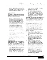
Remove the screws attaching the left 

side panel to the cabinet and remove 

the panel. (Refer to Figures 1 – 3.)

 notice!

The air dryer system will not operate 

properly unless all panels are reinstalled 

after any maintenance work.

Remove compression fitting on 

the elbow attached to the particle 

strainer of the separator assembly 

by turning the hex head nut on the 

fitting. Remove the plastic tubing 

connecting the particle strainer and 

the drain valve solenoid.
Close the shut-off valve on the 

particle strainer, drain the down 

stream line of the particle strainer 

with the PUSH-TO-TEST button on 

the auto drain. Unscrew and clean 

out screen, replace screen and open 

shut-off valve.
Remove lower bowl bracket by 

unfastening the two machine screws 

and nuts that hold the lower bracket 

to the back panel.
Turn the separator bowl 

counterclockwise to remove. A pipe 

wrench may be necessary to remove 

the bowl.

 notice!

When reinstalling the separator bowl, 

make  sure  the  O-ring  is  in  place  on 

the  top  of  the  bowl  and  that  the  O-

ring  seats  properly  on  the  separator 

housing. Air leaks may occur if O-ring 

is not seated.

Clean the bowl assembly with a mild 

soap solution and cold water.
Inspect the drain hoses for any kinks. 

Remove the drain hose inside the 

air dryer system and the drain hose 

outside the unit and blow into the 

a.

b.

c.

d.

e.

f.

g.

line to clear any sediment or foreign 

material from the lines.
Reinstall the moisture separator 

bowl, the lower filter bracket, the 

particle strainer assembly, and the 

two drain hoses. If the separator still 

will not drain, contact Quincy or your 

distributor to order a new separator 

assembly.

Condenser coil cleaning - 

Remove ambient 

filter (if equipped). Remove either the right 

or left side panel screws and panel. Using 

compressed air, blow collected dust and 

contamination off condenser from inside to 

outside.

Hot gas bypass valve adjustment - 

The 

hot gas bypass valve adjustment regulates 

the flow of refrigerant through the heat 

exchanger to maintain the proper suction 

pressure. The suction pressure must be 

maintained within the proper range for 

normal operation. The needle on the 

refrigerant suction pressure gauge should 

be in the blue zone.

Hot gas bypass valve adjustments 

must be made while the unit is 

operating. DO NOT TURN THE UNIT 

OFF.
Remove the left side panel on the 

cabinet. The hot gas bypass valve 

adjustment nut is located on the 

refrigerant discharge line near the 

compressor.
If the suction pressure gauge 

indicator arrow is below 25 PSIG, 

turn the adjusting nut CLOCKWISE. If 

the suction pressure gauge indicator 

needle is above 33 PSIG, turn the 

adjusting nut COUNTERCLOCKWISE. 

Let the unit operate for a few minutes 

and read the suction pressure gauge 

again. Continue to adjust the valve 

until the indicator arrow is in the 

BLUE ZONE between 25 PSIG and 

33 PSIG. Adjust only 1/4 of a turn 

at a time. ALLOW 4 — 5 MINUTES 

BETWEEN ADJUSTMENTS.

h.

a.

b.

c.


Quincy Compressor-QPHT 

13

Back to TOC

Содержание Quincy Compressor QPHT 100

Страница 1: ...s important safety information and should be made available to all personnel who operate and or maintain this product Carefully read this manual before attempting to operate or perform maintenance on this equipment Manual No 65505 2A April 2008 Edition ...

Страница 2: ......

Страница 3: ...eshooting 14 QPHT 25 Parts Lists 15 QPHT 50 Parts Lists 16 QPHT 75 Parts Lists 17 QPHT 100 Parts Lists 18 QPHT 125 Parts Lists 19 QPHT 25 Dimensional 20 QPHT 50 Dimensional 21 QPHT 75 100 125 Dimensional 22 QPHT 25 Wiring Diagram 23 QPHT 50 Wiring Diagram 24 QPHT 75 115V Wiring Diagram 25 QPHT 75 230V Wiring Diagram 26 QPHT 100 125 115V Wiring Diagram 27 QPHT 100 125 230V Wiring Diagram 28 Quincy ...

Страница 4: ......

Страница 5: ...n this manual and posted on the unit Keep this manual near the unit and in a safe place Replace this manual if it becomes torn or dirty and cannot be properly used Please read the Operating Instructions section of this manual before attempting to operate the unit Please read the Maintenance Adjustments and Troubleshooting sections of this manual before beginning any maintenance or service work on ...

Страница 6: ...hemical spills oil solvents and wet floors All of these can damage a hose USE SUITABLE PARTS ACCESSORIES Do not use air pressurized accessories or parts in the air system not suitable for the maximum air pressure used Be sure maximum pressure specified by the accessory manufacturer is well above the working pressure of your compressor RELEASE AIR PRESSURE SLOWLY Fast moving air will stir up dust a...

Страница 7: ...he manufacturer of the material being sprayed Spray in an open area away from flames and electrical equipment Fumes are dangerous Spray in a well ventilated area to keep fumes from collecting and causing health and fire hazards Do not spray in vicinity of open flames or other areas where a spark can cause ignition Do not smoke when spraying paint insecticides or other flammable substances Use a re...

Страница 8: ...ad a pipe nipple on the air outlet connection Install the filter to the pipe nipple with arrow on filter pointing away from air dryer unit Use pipe sealer on both ends of the nipple to facilitate sealing without undue torque pressure Notice Optional coalescing oil filter must be installed with direction arrow facing AWAY from the air dryer system unit If the oil filter is installed backwards disch...

Страница 9: ...d national electrical codes The air dryer system has been tested and shipped with a full charge of oil and refrigerant Inspect the suction pressure gauge located on the front of the unit refer to Figures 1 3 While the unit is idle not operating the refrigerant suction pressure should be within the range of 90 to 130 PSIG If the suction pressure gauge reads 0 PSIG or near 0 PSIG contact Quincy or y...

Страница 10: ...ER YEAR HOT GAS BYPASS VALVE DRAIN SOLENOID VALVE REFRIGERANT SUCTION PRESSURE GAUGE ON OFF SWITCH PUSH TO TEST SWITCH CYCLE TIME DRAIN TIME OPTIONAL AMBIENT FILTER AIR INTAKE ELECTRIC POWER CONNECTION AIR INLET AIR OUTLET OPTIONAL OIL FILTER SIGHT GLASS MOISTURE DRAIN TUBE Figure 1 Model QPHT 25 Quincy Compressor QPHT Back to TOC ...

Страница 11: ...MOISTURE SEPARATOR DRAIN SOLENOID VALVE Y STRAINER CLEANOUT PORT TURN VALVE OFF BEFORE REMOVING CLEAN 4 TIMES PER YEAR FAN MOTOR REFRIGERATION COMPRESSOR HOT GAS BYPASS VALVE AIR FLOW ON OFF SWITCH PUSH TO TEST SWITCH CYCLE TIME DRAIN TIME AIR FLOW REFRIGERANT SUCTION PRESSURE GAUGE Figure 2 Model QPHT 50 Quincy Compressor QPHT Back to TOC ...

Страница 12: ...E DRAIN TIME FAN MOTORS REFRIGERATION COMPRESSOR HOT GAS BYPASS VALVE Y STRAINER CLEANOUT PORT TURN VALVE OFF BEFORE REMOVING CLEAN 4 TIMES PER YEAR DRAIN SOLENOID VALVE DRAIN CONNECTION ELECTRIC POWER CONNECTION OPTIONAL OIL FILTER AIR OUTLET AIR INLET MOISTURE SEPARATOR Figure 3 Model QPHT 75 100 125 Quincy Compressor QPHT Back to TOC ...

Страница 13: ...rocedure should be repeated 3 or 4 times in every 8 hour period of operation The moisture drain valve operates automatically and is controlled with the CYCLE TIME and DRAIN TIME knobs Initially both knobs should be turned counterclockwise to the seven o clock position When using the unit after shipment check both knobs and turn to the seven o clock position if they have been moved The controls are...

Страница 14: ...ight High temperature light Refrigerant suction pressure gauge Drain test button Drain timer adjustment controls 2 Model QPHT 50 Unit Dimensions Length 28 Width 18 Height 30 Flow 50 SCFM Inlet Pressure 175 PSIG 200 PSIG Maximum Ambient Temperature Minimum 55 F 13 C Maximum 100 F 38 C Inlet Temperature 180 F 82 C Maximum Dew Pt Temperature 50 F 2 10 C 1 Refrigerant H P 1 3 Heat Exchanger Material C...

Страница 15: ...nts The ON OFF switch holds a HIGH TEMP light which will turn on if the unit s compressor system malfunctions If the red HIGH TEMP light on this switch is illuminated turn off and unplug the unit for 15 minutes and restart If the light remains on after restarting or it continues to turn on afterwards contact Quincy or your distributor Periodic maintenance The following procedures should be perform...

Страница 16: ...air dryer system Warning Depressurize air dryer system before removing coalescing oil filter bowl Failure to do so will cause the filter to blow off its fitting and cause bodily injury and property damage a Remove the filter bowl the bottom half of the assembly by turning the bowl counterclockwise Clean the bowl and the drain stem with water and a mild soap solution Notice When reinstalling the fi...

Страница 17: ...any sediment or foreign material from the lines Reinstall the moisture separator bowl the lower filter bracket the particle strainer assembly and the two drain hoses If the separator still will not drain contact Quincy or your distributor to order a new separator assembly Condenser coil cleaning Remove ambient filter if equipped Remove either the right or left side panel screws and panel Using com...

Страница 18: ... in the air systems Adjust hot gas bypass valve see Page 12 Low on refrigerant Call for service To confirm freeze up shut off the unit for 15 minutes Air pressure should come back to line pressure Continuous air flow through the moisture drain line Foreign materials lodged on the valve seat Press the PUSH TO TEST switch several times Disconnect the drain lines to the solenoid valve and blow compre...

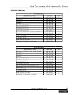
Страница 19: ... Strainer Screen QFT 003845 1 Ambient Filter Optional QRF 000811 2 Coalescing Filter Element Optional CSNE00030 1 230V 1PH 60Hz PART DESCRIPTION PART NO QTY Refrigerant Condensing unit 25 HP R 134A QRF 001226 1 Fan Motor QRF 001277 1 Fan Blade QRF 000538 1 Receiver QRF 003224 1 Capillary Tube Assembly QRF 001182 1 Hot Gas Bypass Valve QVA 000579 1 Power On Off Switch QRF 001983 1 Suction Pressure ...

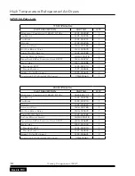
Страница 20: ...trainer Screen QFT 003845 1 Ambient Filter Optional QRF 002641 2 Coalescing Filter Element Optional CSNE00060 1 230V 1PH 60Hz PART DESCRIPTION PART NO QTY Refrigerant Compressor 0 33 HP R 134a 1624 5007 31 1 Fan Motor QRF 000795 1 Fan Blade QRF 000774 1 Receiver QRF 003224 1 Expansion Valve QVA 001784 1 Hot Gas Bypass Valve QVA 000579 1 Power On Off Switch QRF 001983 1 Suction Pressure Gauge QGM 0...

Страница 21: ...Strainer Screen QFT 003845 1 Ambient Filter Optional QRF 002641 2 Coalescing Filter Element Optional CSNE00060 1 230V 1PH 60Hz PART DESCRIPTION PART NO QTY Refrigerant Compressor 0 5 HP R 134A QRF 003110 1 Fan Motor QRF 000795 1 Fan Blade QRF 000774 1 Receiver QRF 003224 1 Expansion Valve QVA 001783 1 Hot Gas Bypass Valve QVA 000579 1 Fan Cycling Switch QRF 002079 1 Power On Off Switch QRF 001983 ...

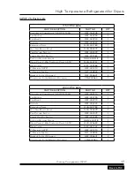
Страница 22: ... Strainer Screen QFT 003845 1 Ambient Filter Optional QRF 002641 2 Coalescing Filter Element Optional CSNE00125 1 230V 1PH 60Hz PART DESCRIPTION PART NO QTY Refrigerant Compressor 0 5 HP R 134A QRF 003111 1 Fan Motor QRF 000795 1 Fan Blade QRF 000774 1 Receiver QRF 003224 1 Expansion Valve QVA 001783 1 Hot Gas Bypass Valve QVA 000579 1 Fan Cycling Switch QRF 002079 1 Power On Off Switch QRF 001983...

Страница 23: ... Strainer Screen QFT 003845 1 Ambient Filter Optional QRF 002641 2 Coalescing Filter Element Optional CSNE00125 1 230V 1PH 60Hz PART DESCRIPTION PART NO QTY Refrigerant Compressor 0 5 HP R 134A QRF 003111 1 Fan Motor QRF 000795 1 Fan Blade QRF 000774 1 Receiver QRF 003224 1 Expansion Valve QVA 001783 1 Hot Gas Bypass Valve QVA 000579 1 Fan Cycling Switch QRF 002079 1 Power On Off Switch QRF 001983...

Страница 24: ...High Temperature Refrigerated Air Dryers QPHT 25 Dimensional 20 Quincy Compressor QPHT Back to TOC ...

Страница 25: ...High Temperature Refrigerated Air Dryers QPHT 50 Dimensional Quincy Compressor QPHT 21 Back to TOC ...

Страница 26: ...High Temperature Refrigerated Air Dryers QPHT 75 100 125 Dimensional 22 Quincy Compressor QPHT Back to TOC ...

Страница 27: ...High Temperature Refrigerated Air Dryers QPHT 25 Wiring Diagram Quincy Compressor QPHT 23 Back to TOC ...

Страница 28: ...High Temperature Refrigerated Air Dryers QPHT 50 Wiring Diagram 24 Quincy Compressor QPHT Back to TOC ...

Страница 29: ...High Temperature Refrigerated Air Dryers QPHT 75 115V Wiring Diagram Quincy Compressor QPHT 25 Back to TOC ...

Страница 30: ...High Temperature Refrigerated Air Dryers QPHT 75 230V Wiring Diagram 26 Quincy Compressor QPHT Back to TOC ...

Страница 31: ...High Temperature Refrigerated Air Dryers QPHT 100 125 115V Wiring Diagram Quincy Compressor QPHT 27 Back to TOC ...

Страница 32: ...High Temperature Refrigerated Air Dryers QPHT 100 125 230V Wiring Diagram 28 Quincy Compressor QPHT Back to TOC ...

Страница 33: ... and storage charges may be applied at the discretion of Seller Accounts past due shall bare interest at the highest rate lawful to contract for but if there is no limit set by law such interest shall be eighteen percent 18 Buyer shall pay all cost and expenses including reasonable attorney s fees incurred in collecting the same and no claim except claims within Seller s warranty of material or wo...

Страница 34: ...o seller freight prepaid for inspection Seller warrants repaired or replaced parts of its own manufacture against defects in materials and workmanship under normal use and service for ninety 90 days or for the remainder of the warranty on the product being repaired This warranty shall not apply and Seller shall not be responsible or liable for a Consequential collateral or special losses or damage...

Страница 35: ...________________________________________________________ ____________________________________________________________________ ____________________________________________________________________ ____________________________________________________________________ ____________________________________________________________________ ___________________________________________________________________...

Страница 36: ...________________________________________________________ ____________________________________________________________________ ____________________________________________________________________ ____________________________________________________________________ ____________________________________________________________________ ___________________________________________________________________...

Страница 37: ......
Страница 38: ... 2008 Quincy Compressor an EnPro Industries company All Rights Reserved Litho in U S A Quincy Compressor Products 217 222 7700 E mail info quincycompressor com Website www quincycompressor com ...

Отзывы: