Code: I.H4.V10.3003
Installation and Maintenance Manual
Version: 07
14 / 66
Ennera Energy and Mobility, S.L.
This document contains confidential information which is property of Ennera Energy and Mobility, S.L. The copy, transmission or use by other people, of the whole document or
part of its contents, is not allowed without written permission from Ennera Energy and Mobility S.L.
6.
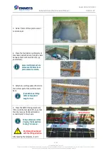
Put the tower first section back to
previous position and tight fully the 3
M30 nuts of the tower base.
Once tightened, ensure
again that the tower fixing
bolts pass freely through
the first section holes as
shown on step 5.
7.
With the tower first section in
parallel to the ground, pass the cable
guide (TW-4) through it.
The cable guide helps to
pass the tower cable
through the whole tower.
8.
Insert the tower second section over
the first section. To do this:
•
Ensure that the weld seam of the
new section is aligned with the
previous section.
•
Pass the guide through the new
section.
•
With tape, mark the interference
distance. In this case, at 520mm
from the edge.
•
Apply some grease or oil over the
lower up section (interference area).
•
Fit manually first and second tower
sections.
The interference distance is the distance that one
section should be introduced in the previous one.
9.
Adjust both sections until
interference distance mark is reached:
•
Put both tractels hooks on the new
section edges.
•
Secure both hooks of the other side
to the base section.
•
Using the tractels adjust joined
sections until the interference
distance mark is reached.
In case that the mark
cannot be reached, put a
wooden block across the
upper section and hit it
with a mallet.
Weld seam indicator
520 mm
TW-4

