


AM-5175
ENMET Corporation
3
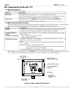
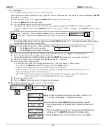
2.3 Circuit Board Features
The Display Panel is attached by a cable and is released by unscrewing the 4 screws located in the corners. After releasing the
panel, it is swung upward, exposing the interior of the enclosure. The Circuit Board is mounted at the back surface of the
enclosure interior. Features are shown in Figure 2.
Feature
Description
Relay Terminals:
J14, J15, J16, J17
This group of terminals is located on the Circuit Board.
For the contacts for each of three alarm relays, and for the contacts of a fault relay.
See Section 3.3
Terminal J12
For
V
DC
back-up power in and the 4-20 mA output. See Section 3.1.2
Sensor Terminal J8
Sensor connection, See Section 3.2
Data Terminal J19
RS-485 input/output
Potentiometer 2, 3 & 4
Not used in
AM-5175
Do Not Adjust
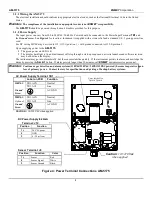
Figure 2: AM-5175 Circuit Board Features
Relay Terminals
J14, J15, J16, J17
Relays
K1, K2, K3, K4
Terminal J12
DC Power In
4-20mA Output
RS-485 Input/Output
Terminal J19
Sensor Connection
Terminal J8