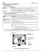


AM-5175
ENMET Corporation
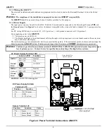
16
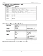
6.0 Accessory and Replacement Parts
ENMET
accessory part numbers:
Part number
Description
03620-022
Calibration Cup
04834-004
Calibration Regulator Assembly for Steel Cylinder
03219-100
Gas Cylinder, 100 ppm CO in air, (34 Liter, Steel Cylinders)
03296-209
Gas Cylinder, Zero Gas, 20.9% oxygen in nitrogen, (34 Liter, Steel Cylinders)
04834-001
Calibration Regulator Assembly for Aluminum Cylinder
03314-020
Gas Cylinder, 20 ppm H
2
S in N
2
, (34 Liter, Aluminum Cylinders)
67028-0200
Sensor H
2
S
67028-1100
Sensor O
2
67028-1200
Sensor CO
73083-000
Carry Case
7.0 Technical Data and Specifications
Electrical Power
15 Amp fused branch circuit
100-240
V
AC
0.45A, 50/60 Hz
0.6A, 24
V
DC
Operation
Temperature:
-20
°
to +40
°
C (-4
°
to +104
°
F)
Relative Humidity
10-99% RH, non-condensing
Mechanical
Dimensions:
7.1 x 5.1 x 3 in(180x130x75mm)
Weight:
2 lbs (0.9 kg)
Material:
Polycarbonate
Strain relief:
3 - 6.5mm OD
Outputs
Relays:
SPDT
Resistive Load Inductive Load
10A at 110 V
AC
7.5A at 110 V
AC
10A at 30 V
DC
5A at 30 V
DC
Analog:
4-20mA
Digital:
RS-485-modbus
Audio:
105 dB at 30cm/12in
N
OTE
:
All specifications stated in this manual may change without notice.