


275
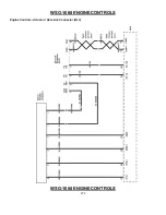
WSG-1068 ENGINE CONTROLS
DIAGNOSIS AND TESTING
Diagnostic Approach
Use the following step by step approach when
diagnosing an engine performance problem:
1. Verify the concern and determine if it is a deviation
from normal operation.
2. Once the concern has been verified, preliminary
checks can be done. Conduct a thorough visual
inspection, be alert for unusual sounds or odors,
and gather diagnostic trouble code (DTC)
information.
3. If a diagnostic trouble code (DTC) is stored, follow
the designated DTC chart exactly to make an
effective repair.
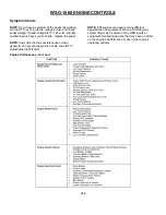
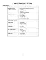
4. If no DTC is stored, select the symptom from the
symptom charts and follow the suggestions to
complete
the
repair.
5. If no matching symptom is available, analyze the
complaint and develop a plan for diagnostics
utilizing the wiring diagrams, technical
assistance and repair history.
6. Some diagnostic charts contain diagnostic aids
which give additional information about a system.
Be sure to use all of the information that is available to you.
GCP Diagnostic Overview
FORD Diagnostic Trouble Codes are set when the
FORD system GCP runs a diagnostic self-test and the
test fails. When a DTC is set, the FORD system GCP
will illuminate the Malfunction Indicator Lamp (MIL) on
the instrument panel and save the code in memory. The
FORD system GCP will continue to run the self-test
unless the DTC is an oxygen sensor lean, oxygen
sensor rich, or a GCP related DTC. If the system
continues to fail the test, the lamp will stay illuminated
and the DTC is current (ACTIVE). All DTC’s are stored
as historical faults until they are cleared. All DTC’s
except the GCP related DTC’s will automatically clear
from memory if the DTC does not reset within 50
consecutive engine run cycles.
While a Diagnostic Trouble Code is current for a sensor,
the FORD system GCP may assign a default limp home
value and use that value in its control algorithms. All of
the FORD system diagnostic self-tests run continuously
during normal engine operation.
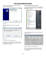
The Diagnostic Trouble Codes can be read by using
either the Malfunction Indicator Lamp (MIL) or a Laptop
computer. Refer to Using a Laptop Computer to
Diagnose the FORD System and Using a Diagnostic
Jumper to Diagnose the FORD System, located in this
section. Diagnostic Trouble Codes can be cleared from
memory with a laptop computer or by turning the ignition
key to the OFF position and removing the FORD system
main power fuse (F3) for 15 seconds.
If more than one DTC is detected, begin with the lowest
number DTC and diagnose each problem to correction
unless directed to do otherwise by the fault tree. The
DTC’s are numbered in order of importance. Having
DTC 112 and DTC 122, both concerning the oxygen
sensor, is possible. By repairing DTC 112 first, the
problem causing the DTC 122 may also be corrected.
On-Board Diagnostics - GCP
The diagnostic tests and circuit charts are designed to
assist the technician to locate a faulty circuit or
component through a process of logical decisions. The
tests and charts are prepared with the requirement that
the engine functioned correctly at the time of assembly
and that there were not multiple faults present.
There is a continuous self-diagnosis on certain control
functions. This diagnostic capability is complimented by
the diagnostic procedures contained in this section. The
language for communicating the source of the
malfunction is a system of diagnostic trouble codes.
When a malfunction is detected by the Engine Control
Module (GCP), a Diagnostic Trouble Code (DTC) is set
and the Malfunction Indicator (MIL) lamp will be
illuminated (refer to MIL DTC Retrieval Procedure for
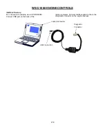
process description) -- Refer to“Diagnosis Using a
Personal Computer” on page 26 or Palm Pilot
Diagnosis, for information regarding performing GCP
and engine control system diagnosis.
Engine Control Module (GCP) Limp Home
Mode Strategy
The GCP has four settings for limp home mode.
Depending on what Diagnostic Trouble Code (DTC) is
set, one or more of the limp home modes will be in
effect. The four limp home modes are as follows:
Power Derate 1
The actuator is limited to a maximum opening of 50%. If
“Power Derate 1” is active, it will remain active until the
active DTC goes away.
The following DTC’s will cause Power Derate 1 to take
affect:
DTC 1521: CHT/ECT higher than expected (CHT/ECT is
greater than 240 °F).
DTC 111: IAT higher than expected 1. (IAT is greater
than 200°F).
DTC 327: Knock sensor open. (1.6L and 4.2L only)
DTC 326: Excessive knock signal. (1.6L and 4.2L only)
DTC 2122: FPP1 high voltage.
DTC 2123: FPP1 low voltage.
DTC 2128: FPP2 high voltage.
DTC 2127: FPP2 low voltage.
DTC 1531: IVS/Brake interlock failure.
Power Derate 2
Содержание WSG-1068
Страница 1: ...WSG 1068 6 8 LITER INDUSTRIAL ENGINE SERVICE MANUAL EDI 1050180 March 2009 ...
Страница 12: ...6 WSG 1068 GENERAL INFORMATION DIAGNOSIS AND TESTING Special Tools ...
Страница 14: ...8 WSG 1068 GENERAL INFORMATION Symptom Chart Condition Possible Source Action ...
Страница 15: ...9 WSG 1068 GENERAL INFORMATION ...
Страница 46: ...30 WSG 1068 ENGINE INDEX CONT Subject Page Specifications Torque Specifications General Specifications 171 171 ...
Страница 48: ...32 WSG 1068 ENGINE Module View ...
Страница 49: ...33 WSG 1068 ENGINE Engine Intake Components ...
Страница 50: ...34 WSG 1068 ENGINE ...
Страница 51: ...35 WSG 1068 ENGINE Low End Components ...
Страница 52: ...36 WSG 1068 ENGINE ...
Страница 53: ...37 WSG 1068 ENGINE Upper End Components ...
Страница 54: ...38 WSG 1068 ENGINE ...
Страница 55: ...39 WSG 1068 ENGINE Major Front End Components ...
Страница 56: ...40 WSG 1068 ENGINE DIAGNOSIS AND TESTING Refer to Section 01 for basic mechanical concerns ...
Страница 65: ...49 WSG 1068 ENGINE 4 Tighten the nuts and bolts in the sequence shown ...
Страница 68: ...52 WSG 1068 ENGINE 4 Tighten the bolts in the sequence shown 5 Reinstall the PCV valve ...
Страница 75: ...59 WSG 1068 ENGINE ...
Страница 87: ...71 WSG 1068 ENGINE Camshaft Assembly Timing Mark Alignment ...
Страница 88: ...72 WSG 1068 ENGINE Timing Chains Camshaft Gears and Crankshaft Gears Alignment ...
Страница 98: ...82 WSG 1068 ENGINE Exhaust Manifold RH Installation 1 Follow the removal procedure in reverse order ...
Страница 106: ...90 WSG 1068 ENGINE 5 Remove the flywheel inspection plate 6 Remove the bolts and partially lower the oil pan 6675 ...
Страница 120: ...104 WSG 1068 ENGINE Engine Disassembly 1 With the engine on the engine stand remove the engine wiring harness ...
Страница 129: ...113 WSG 1068 ENGINE 20 Remove the timing chain guides 6K297 Remove the bolts Remove the timing chain guides ...
Страница 137: ...121 WSG 1068 ENGINE 1 Remove the Camshaft Holding Tool from the camshaft 6250 ...
Страница 143: ...127 WSG 1068 ENGINE 10 Install the roller followers 11 Remove the Valve Spring Spacer ...
Страница 155: ...139 WSG 1068 ENGINE 35 Install the timing chain guides 6K297 ...
Страница 167: ...151 WSG 1068 ENGINE 68 Position the water pump pulley 8509 on the water pump and install the bolts ...
Страница 172: ...156 WSG 1068 ENGINE SPECIFICATIONS ...
Страница 173: ...157 WSG 1068 ENGINE ...
Страница 174: ...158 WSG 1068 ENGINE ...
Страница 180: ...164 WSG 1068 IGNITION SYSTEM ...
Страница 188: ...172 WSG 1068 IGNITION SYSTEM Firing Order ...
Страница 190: ...174 WSG 1068 IGNITION SYSTEM Harness Connector Pinout Description I O Input Output ...
Страница 194: ...178 WSG 1068 IGNITION SYSTEM Engine Controls ...
Страница 195: ...179 WSG 1068 IGNITION SYSTEM Engine Sensors part of SK2U1L 12A200 BA ...
Страница 197: ...181 WSG 1068 IGNITION SYSTEM 90 Pin GCP Connector ...
Страница 199: ...183 WSG 1068 IGNITION SYSTEM ...
Страница 204: ...188 WSG 1068 FUEL SYSTEM ...
Страница 206: ...190 WSG 1068 COOLING SYSTEM INDEX CONT Subject Specifications General Specifications Torque Specifications Page 234 234 ...
Страница 225: ...209 WSG 1068 COOLING SYSTEM CHT Sensor Data Temperature Sensor Characteristics ...
Страница 229: ...213 WSG 1068 COOLING SYSTEM PINPOINT TEST A LOSS OF COOLANT ...
Страница 230: ...214 WSG 1068 COOLING SYSTEM PINPOINT TEST A LOSS OF COOLANT Continued ...
Страница 231: ...215 WSG 1068 COOLING SYSTEM PINPOINT TEST A LOSS OF COOLANT Continued PINPOINT TEST B THE ENGINE OVERHEATS ...
Страница 232: ...216 WSG 1068 COOLING SYSTEM PINPOINT TEST B THE ENGINE OVERHEATS Continued ...
Страница 233: ...217 WSG 1068 COOLING SYSTEM ...
Страница 234: ...218 PINPOINT TEST B THE ENGINE OVERHEATS Continued WSG 1068 COOLING SYSTEM ...
Страница 235: ...219 PINPOINT TEST C THE ENGINE DOES NOT REACH NORMAL OPERATING TEMPERATURE WSG 1068 COOLING SYSTEM ...
Страница 239: ...223 WSG 1068 CHARGING SYSTEM DIAGNOSIS AND TESTING Recommended Accessory Wiring ...
Страница 243: ...227 WSG 1068 CHARGING SYSTEM Symptom Chart ...
Страница 245: ...229 WSG 1068 CHARGING SYSTEM ...
Страница 250: ...234 WSG 1068 CHARGING SYSTEM SPECIFICATIONS Torque Specifications Generator Parts Cross Reference Special Tools ...
Страница 259: ...243 WSG 1068 STARTER SYSTEM ...
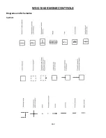
Страница 278: ...262 WSG 1068 ENGINE CONTROLS Diagrams and Schematics Symbols ...
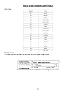
Страница 279: ...263 WSG 1068 ENGINE CONTROLS GCP Power Distribution Box ...
Страница 281: ...265 WSG 1068 ENGINE CONTROLS Power Distribution ...
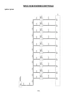
Страница 282: ...266 WSG 1068 ENGINE CONTROLS Ignition System ...
Страница 283: ...267 WSG 1068 ENGINE CONTROLS Starting System ...
Страница 284: ...268 WSG 1068 ENGINE CONTROLS Charging System ...
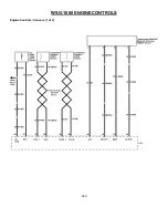
Страница 285: ...269 WSG 1068 ENGINE CONTROLS Engine Controls Sensors 1 of 2 ...
Страница 286: ...270 WSG 1068 ENGINE CONTROLS Engine Controls Sensors 2 of 2 ...
Страница 287: ...271 WSG 1068 ENGINE CONTROLS Fuel Injectors ...
Страница 288: ...272 WSG 1068 ENGINE CONTROLS Engine Controls Actuator Data Link Connector DLC WSG 1068 ENGINE CONTROLS ...
Страница 289: ...273 Engine Controls Dry Fuel EPR ...
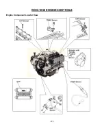
Страница 290: ...274 WSG 1068 ENGINE CONTROLS Engine Component Locator View ...
Страница 305: ...289 WSG 1068 ENGINE CONTROLS Engine Performance While Under Load ...
Страница 306: ...290 WSG 1068 ENGINE CONTROLS Engine Concerns ...
Страница 315: ...299 WSG 1068 ENGINE CONTROLS SPECIFICATIONS ...
Страница 320: ...304 WSG 1068 METRICS ENGLISH METRIC CONVERSION ...
Страница 321: ...305 WSG 1068 METRICS DECIMAL AND METRIC EQUIVALENTS TORQUE CONVERSION ...
Страница 323: ...307 WSG 1068 METRICS ...
Страница 324: ...308 WSG 1068 METRICS ...
Страница 325: ...309 WSG 1068 METRICS ...
Страница 326: ...310 WSG 1068 METRICS ...
Страница 327: ...311 WSG 1068 METRICS ...
Страница 328: ...312 WSG 1068 METRICS ...
Страница 329: ...313 WSG 1068 METRICS ...
Страница 330: ...314 ...