


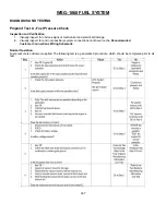


198
WSG-1068 COOLING SYSTEM
REMOVAL AND INSTALLATION
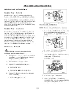
Radiator Hose - Removal
Radiator hoses should be replaced whenever they
become cracked, rotted or have a tendency to collapse.
Drain the radiator into appropriate container then loosen
the clamps at each end of the hose to be removed. Slide
the hose off the radiator connection and the engine
water outlet connection (upper hose) or the water pump
connection (lower hose).
Radiator Hose - Installation
Position the clamps at least 1/8 inch from each end of
the hose. Coat the connection areas with an approved
water-resistant sealer and slide the hose on the
connection. Make sure the clamps are beyond the bead
and placed in the center of the clamping surface of the
connections. Tighten the clamps. Fill the radiator with
the recommended permanent antifreeze and water
50/50 mixture. Operate the engine for several minutes,
then check the hoses and connections for leaks.
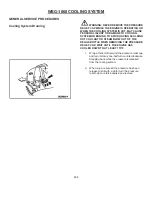
Thermostat - Removal
WARNING: AVOID INJURY FROM HOT
COOLANT WHEN ENGINE IS HOT.
1. Partially drain the cooling system. For additional
information, refer to Cooling System Draining,
Filling and Flushing in this section.
2. Disconnect the upper radiator hose.
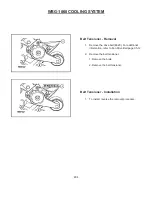
3. Remove the water outlet connection.
Remove
the
bolts.
Remove the water outlet connection.
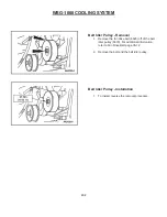
4. Remove
the
(
B
) O-ring seal and the (
A
) water
thermostat
(8575).
Discard the (
B
) O-ring seal.
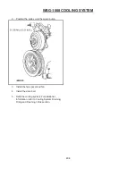
Thermostat - Installation
NOTE:
Thermostat must be installed as illustrated.
1. Install the (B) water thermostat and use a new
(
A
) Oring seal to position the (
B
) water
thermostat in the (
C
) upper intake manifold
(9424).
2. Install the water outlet connection.
1. Position the (
A
) water outlet connection on
the
(
B
) upper intake manifold.
2. Install the bolts.
3. Connect the upper radiator hose.
4. Fill the cooling system. For additional
information, refer to Cooling System Draining,
Filling and Flushing in this section.
Содержание WSG-1068
Страница 1: ...WSG 1068 6 8 LITER INDUSTRIAL ENGINE SERVICE MANUAL EDI 1050180 March 2009 ...
Страница 12: ...6 WSG 1068 GENERAL INFORMATION DIAGNOSIS AND TESTING Special Tools ...
Страница 14: ...8 WSG 1068 GENERAL INFORMATION Symptom Chart Condition Possible Source Action ...
Страница 15: ...9 WSG 1068 GENERAL INFORMATION ...
Страница 46: ...30 WSG 1068 ENGINE INDEX CONT Subject Page Specifications Torque Specifications General Specifications 171 171 ...
Страница 48: ...32 WSG 1068 ENGINE Module View ...
Страница 49: ...33 WSG 1068 ENGINE Engine Intake Components ...
Страница 50: ...34 WSG 1068 ENGINE ...
Страница 51: ...35 WSG 1068 ENGINE Low End Components ...
Страница 52: ...36 WSG 1068 ENGINE ...
Страница 53: ...37 WSG 1068 ENGINE Upper End Components ...
Страница 54: ...38 WSG 1068 ENGINE ...
Страница 55: ...39 WSG 1068 ENGINE Major Front End Components ...
Страница 56: ...40 WSG 1068 ENGINE DIAGNOSIS AND TESTING Refer to Section 01 for basic mechanical concerns ...
Страница 65: ...49 WSG 1068 ENGINE 4 Tighten the nuts and bolts in the sequence shown ...
Страница 68: ...52 WSG 1068 ENGINE 4 Tighten the bolts in the sequence shown 5 Reinstall the PCV valve ...
Страница 75: ...59 WSG 1068 ENGINE ...
Страница 87: ...71 WSG 1068 ENGINE Camshaft Assembly Timing Mark Alignment ...
Страница 88: ...72 WSG 1068 ENGINE Timing Chains Camshaft Gears and Crankshaft Gears Alignment ...
Страница 98: ...82 WSG 1068 ENGINE Exhaust Manifold RH Installation 1 Follow the removal procedure in reverse order ...
Страница 106: ...90 WSG 1068 ENGINE 5 Remove the flywheel inspection plate 6 Remove the bolts and partially lower the oil pan 6675 ...
Страница 120: ...104 WSG 1068 ENGINE Engine Disassembly 1 With the engine on the engine stand remove the engine wiring harness ...
Страница 129: ...113 WSG 1068 ENGINE 20 Remove the timing chain guides 6K297 Remove the bolts Remove the timing chain guides ...
Страница 137: ...121 WSG 1068 ENGINE 1 Remove the Camshaft Holding Tool from the camshaft 6250 ...
Страница 143: ...127 WSG 1068 ENGINE 10 Install the roller followers 11 Remove the Valve Spring Spacer ...
Страница 155: ...139 WSG 1068 ENGINE 35 Install the timing chain guides 6K297 ...
Страница 167: ...151 WSG 1068 ENGINE 68 Position the water pump pulley 8509 on the water pump and install the bolts ...
Страница 172: ...156 WSG 1068 ENGINE SPECIFICATIONS ...
Страница 173: ...157 WSG 1068 ENGINE ...
Страница 174: ...158 WSG 1068 ENGINE ...
Страница 180: ...164 WSG 1068 IGNITION SYSTEM ...
Страница 188: ...172 WSG 1068 IGNITION SYSTEM Firing Order ...
Страница 190: ...174 WSG 1068 IGNITION SYSTEM Harness Connector Pinout Description I O Input Output ...
Страница 194: ...178 WSG 1068 IGNITION SYSTEM Engine Controls ...
Страница 195: ...179 WSG 1068 IGNITION SYSTEM Engine Sensors part of SK2U1L 12A200 BA ...
Страница 197: ...181 WSG 1068 IGNITION SYSTEM 90 Pin GCP Connector ...
Страница 199: ...183 WSG 1068 IGNITION SYSTEM ...
Страница 204: ...188 WSG 1068 FUEL SYSTEM ...
Страница 206: ...190 WSG 1068 COOLING SYSTEM INDEX CONT Subject Specifications General Specifications Torque Specifications Page 234 234 ...
Страница 225: ...209 WSG 1068 COOLING SYSTEM CHT Sensor Data Temperature Sensor Characteristics ...
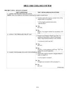
Страница 229: ...213 WSG 1068 COOLING SYSTEM PINPOINT TEST A LOSS OF COOLANT ...
Страница 230: ...214 WSG 1068 COOLING SYSTEM PINPOINT TEST A LOSS OF COOLANT Continued ...
Страница 231: ...215 WSG 1068 COOLING SYSTEM PINPOINT TEST A LOSS OF COOLANT Continued PINPOINT TEST B THE ENGINE OVERHEATS ...
Страница 232: ...216 WSG 1068 COOLING SYSTEM PINPOINT TEST B THE ENGINE OVERHEATS Continued ...
Страница 233: ...217 WSG 1068 COOLING SYSTEM ...
Страница 234: ...218 PINPOINT TEST B THE ENGINE OVERHEATS Continued WSG 1068 COOLING SYSTEM ...
Страница 235: ...219 PINPOINT TEST C THE ENGINE DOES NOT REACH NORMAL OPERATING TEMPERATURE WSG 1068 COOLING SYSTEM ...
Страница 239: ...223 WSG 1068 CHARGING SYSTEM DIAGNOSIS AND TESTING Recommended Accessory Wiring ...
Страница 243: ...227 WSG 1068 CHARGING SYSTEM Symptom Chart ...
Страница 245: ...229 WSG 1068 CHARGING SYSTEM ...
Страница 250: ...234 WSG 1068 CHARGING SYSTEM SPECIFICATIONS Torque Specifications Generator Parts Cross Reference Special Tools ...
Страница 259: ...243 WSG 1068 STARTER SYSTEM ...
Страница 278: ...262 WSG 1068 ENGINE CONTROLS Diagrams and Schematics Symbols ...
Страница 279: ...263 WSG 1068 ENGINE CONTROLS GCP Power Distribution Box ...
Страница 281: ...265 WSG 1068 ENGINE CONTROLS Power Distribution ...
Страница 282: ...266 WSG 1068 ENGINE CONTROLS Ignition System ...
Страница 283: ...267 WSG 1068 ENGINE CONTROLS Starting System ...
Страница 284: ...268 WSG 1068 ENGINE CONTROLS Charging System ...
Страница 285: ...269 WSG 1068 ENGINE CONTROLS Engine Controls Sensors 1 of 2 ...
Страница 286: ...270 WSG 1068 ENGINE CONTROLS Engine Controls Sensors 2 of 2 ...
Страница 287: ...271 WSG 1068 ENGINE CONTROLS Fuel Injectors ...
Страница 288: ...272 WSG 1068 ENGINE CONTROLS Engine Controls Actuator Data Link Connector DLC WSG 1068 ENGINE CONTROLS ...
Страница 289: ...273 Engine Controls Dry Fuel EPR ...
Страница 290: ...274 WSG 1068 ENGINE CONTROLS Engine Component Locator View ...
Страница 305: ...289 WSG 1068 ENGINE CONTROLS Engine Performance While Under Load ...
Страница 306: ...290 WSG 1068 ENGINE CONTROLS Engine Concerns ...
Страница 315: ...299 WSG 1068 ENGINE CONTROLS SPECIFICATIONS ...
Страница 320: ...304 WSG 1068 METRICS ENGLISH METRIC CONVERSION ...
Страница 321: ...305 WSG 1068 METRICS DECIMAL AND METRIC EQUIVALENTS TORQUE CONVERSION ...
Страница 323: ...307 WSG 1068 METRICS ...
Страница 324: ...308 WSG 1068 METRICS ...
Страница 325: ...309 WSG 1068 METRICS ...
Страница 326: ...310 WSG 1068 METRICS ...
Страница 327: ...311 WSG 1068 METRICS ...
Страница 328: ...312 WSG 1068 METRICS ...
Страница 329: ...313 WSG 1068 METRICS ...
Страница 330: ...314 ...