


236
WSG-1068 STARTER SYSTEM
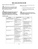
GENERAL INFORMATION
The function of the starting system is to crank the engine
at a speed fast enough to permit the engine to start.
Heavy cables, connectors, and switches are used in the
starting system because of the large current required by
the starter while it is cranking the engine. The amount of
resistance in the starting circuit must be kept to an
absolute minimum to provide maximum current for
starter operation. A discharged or damaged battery,
loose or corroded connections, or partially broken cables
will result in slower than normal cranking speeds, and
may even prevent the starter from cranking the engine.
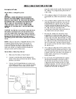
The starting system includes the permanent magnet
gearreduction starter motor with a solenoid-actuated
drive, the battery, a remote control starter switch (part of
the ignition switch), the starter relay, the heavy circuit
wiring, and may include starter lock-out, controlled by
the GCP through a starter lockout relay.
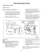
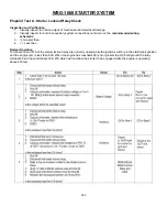
Field Service
Sequence Of Operation
1. The ignition switch is turned to the START
position.
2. A remote starter relay is energized, which
provides voltage to the starter solenoid. The
starter solenoid is energized, creating a
magnetic field in the solenoid coil.
3. The iron plunger core is drawn into the solenoid
coil.
4. A lever connected to the drive assembly
engages the drive pinion gear to the flywheel
ring rear.
5. When the iron plunger core is all the way into
the coil, its contact disc closes the circuit
between the battery and the motor terminals.
6. The current flows to the motor, and the drive
pinion gear drives the flywheel and the engine
crankshaft.
7. As current flows to the motor, the solenoid pull in
coil is bypassed.
8. The hold-in coil keeps the drive pinion gear
engaged with the flywheel.
9. The gear remains engaged until the ignition
switch is released from the START position.
NOTE:
The GCP is programmed to lock the starter out
when the engine is operating over 600 rpm and the
following sequence takes place:
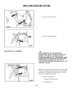
Starter Lockout Relay
See page 07-6 for further details.
1. During start up with key in the on position 12V
(B+) is applied to relay PIN 72 of the GCP (Lt
Gn/ Pr).
2. With ignition switch turned to the crank position,
current flows from ignition switch to relay circuit
87A (LB/Pink) 16G through relay and out circuit
30 (LB/Pink) 16G to starter solenoid.
3. The starter than should respond as in steps 2
through 9. The GCP keeps the starter relay
closed until it reads 400+ engine rpm. Over 600
rpm the GCP grounds circuit causing the relay to
open. This will prevent starter engagement while
engine is running.
NOTE
: An overrunning clutch in the drive assembly
protects the starter from the excessive speeds during
the brief period before the driver releases the ignition
switch from the START position (as the engine starts).
Содержание WSG-1068
Страница 1: ...WSG 1068 6 8 LITER INDUSTRIAL ENGINE SERVICE MANUAL EDI 1050180 March 2009 ...
Страница 12: ...6 WSG 1068 GENERAL INFORMATION DIAGNOSIS AND TESTING Special Tools ...
Страница 14: ...8 WSG 1068 GENERAL INFORMATION Symptom Chart Condition Possible Source Action ...
Страница 15: ...9 WSG 1068 GENERAL INFORMATION ...
Страница 46: ...30 WSG 1068 ENGINE INDEX CONT Subject Page Specifications Torque Specifications General Specifications 171 171 ...
Страница 48: ...32 WSG 1068 ENGINE Module View ...
Страница 49: ...33 WSG 1068 ENGINE Engine Intake Components ...
Страница 50: ...34 WSG 1068 ENGINE ...
Страница 51: ...35 WSG 1068 ENGINE Low End Components ...
Страница 52: ...36 WSG 1068 ENGINE ...
Страница 53: ...37 WSG 1068 ENGINE Upper End Components ...
Страница 54: ...38 WSG 1068 ENGINE ...
Страница 55: ...39 WSG 1068 ENGINE Major Front End Components ...
Страница 56: ...40 WSG 1068 ENGINE DIAGNOSIS AND TESTING Refer to Section 01 for basic mechanical concerns ...
Страница 65: ...49 WSG 1068 ENGINE 4 Tighten the nuts and bolts in the sequence shown ...
Страница 68: ...52 WSG 1068 ENGINE 4 Tighten the bolts in the sequence shown 5 Reinstall the PCV valve ...
Страница 75: ...59 WSG 1068 ENGINE ...
Страница 87: ...71 WSG 1068 ENGINE Camshaft Assembly Timing Mark Alignment ...
Страница 88: ...72 WSG 1068 ENGINE Timing Chains Camshaft Gears and Crankshaft Gears Alignment ...
Страница 98: ...82 WSG 1068 ENGINE Exhaust Manifold RH Installation 1 Follow the removal procedure in reverse order ...
Страница 106: ...90 WSG 1068 ENGINE 5 Remove the flywheel inspection plate 6 Remove the bolts and partially lower the oil pan 6675 ...
Страница 120: ...104 WSG 1068 ENGINE Engine Disassembly 1 With the engine on the engine stand remove the engine wiring harness ...
Страница 129: ...113 WSG 1068 ENGINE 20 Remove the timing chain guides 6K297 Remove the bolts Remove the timing chain guides ...
Страница 137: ...121 WSG 1068 ENGINE 1 Remove the Camshaft Holding Tool from the camshaft 6250 ...
Страница 143: ...127 WSG 1068 ENGINE 10 Install the roller followers 11 Remove the Valve Spring Spacer ...
Страница 155: ...139 WSG 1068 ENGINE 35 Install the timing chain guides 6K297 ...
Страница 167: ...151 WSG 1068 ENGINE 68 Position the water pump pulley 8509 on the water pump and install the bolts ...
Страница 172: ...156 WSG 1068 ENGINE SPECIFICATIONS ...
Страница 173: ...157 WSG 1068 ENGINE ...
Страница 174: ...158 WSG 1068 ENGINE ...
Страница 180: ...164 WSG 1068 IGNITION SYSTEM ...
Страница 188: ...172 WSG 1068 IGNITION SYSTEM Firing Order ...
Страница 190: ...174 WSG 1068 IGNITION SYSTEM Harness Connector Pinout Description I O Input Output ...
Страница 194: ...178 WSG 1068 IGNITION SYSTEM Engine Controls ...
Страница 195: ...179 WSG 1068 IGNITION SYSTEM Engine Sensors part of SK2U1L 12A200 BA ...
Страница 197: ...181 WSG 1068 IGNITION SYSTEM 90 Pin GCP Connector ...
Страница 199: ...183 WSG 1068 IGNITION SYSTEM ...
Страница 204: ...188 WSG 1068 FUEL SYSTEM ...
Страница 206: ...190 WSG 1068 COOLING SYSTEM INDEX CONT Subject Specifications General Specifications Torque Specifications Page 234 234 ...
Страница 225: ...209 WSG 1068 COOLING SYSTEM CHT Sensor Data Temperature Sensor Characteristics ...
Страница 229: ...213 WSG 1068 COOLING SYSTEM PINPOINT TEST A LOSS OF COOLANT ...
Страница 230: ...214 WSG 1068 COOLING SYSTEM PINPOINT TEST A LOSS OF COOLANT Continued ...
Страница 231: ...215 WSG 1068 COOLING SYSTEM PINPOINT TEST A LOSS OF COOLANT Continued PINPOINT TEST B THE ENGINE OVERHEATS ...
Страница 232: ...216 WSG 1068 COOLING SYSTEM PINPOINT TEST B THE ENGINE OVERHEATS Continued ...
Страница 233: ...217 WSG 1068 COOLING SYSTEM ...
Страница 234: ...218 PINPOINT TEST B THE ENGINE OVERHEATS Continued WSG 1068 COOLING SYSTEM ...
Страница 235: ...219 PINPOINT TEST C THE ENGINE DOES NOT REACH NORMAL OPERATING TEMPERATURE WSG 1068 COOLING SYSTEM ...
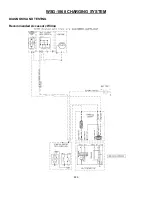
Страница 239: ...223 WSG 1068 CHARGING SYSTEM DIAGNOSIS AND TESTING Recommended Accessory Wiring ...
Страница 243: ...227 WSG 1068 CHARGING SYSTEM Symptom Chart ...
Страница 245: ...229 WSG 1068 CHARGING SYSTEM ...
Страница 250: ...234 WSG 1068 CHARGING SYSTEM SPECIFICATIONS Torque Specifications Generator Parts Cross Reference Special Tools ...
Страница 259: ...243 WSG 1068 STARTER SYSTEM ...
Страница 278: ...262 WSG 1068 ENGINE CONTROLS Diagrams and Schematics Symbols ...
Страница 279: ...263 WSG 1068 ENGINE CONTROLS GCP Power Distribution Box ...
Страница 281: ...265 WSG 1068 ENGINE CONTROLS Power Distribution ...
Страница 282: ...266 WSG 1068 ENGINE CONTROLS Ignition System ...
Страница 283: ...267 WSG 1068 ENGINE CONTROLS Starting System ...
Страница 284: ...268 WSG 1068 ENGINE CONTROLS Charging System ...
Страница 285: ...269 WSG 1068 ENGINE CONTROLS Engine Controls Sensors 1 of 2 ...
Страница 286: ...270 WSG 1068 ENGINE CONTROLS Engine Controls Sensors 2 of 2 ...
Страница 287: ...271 WSG 1068 ENGINE CONTROLS Fuel Injectors ...
Страница 288: ...272 WSG 1068 ENGINE CONTROLS Engine Controls Actuator Data Link Connector DLC WSG 1068 ENGINE CONTROLS ...
Страница 289: ...273 Engine Controls Dry Fuel EPR ...
Страница 290: ...274 WSG 1068 ENGINE CONTROLS Engine Component Locator View ...
Страница 305: ...289 WSG 1068 ENGINE CONTROLS Engine Performance While Under Load ...
Страница 306: ...290 WSG 1068 ENGINE CONTROLS Engine Concerns ...
Страница 315: ...299 WSG 1068 ENGINE CONTROLS SPECIFICATIONS ...
Страница 320: ...304 WSG 1068 METRICS ENGLISH METRIC CONVERSION ...
Страница 321: ...305 WSG 1068 METRICS DECIMAL AND METRIC EQUIVALENTS TORQUE CONVERSION ...
Страница 323: ...307 WSG 1068 METRICS ...
Страница 324: ...308 WSG 1068 METRICS ...
Страница 325: ...309 WSG 1068 METRICS ...
Страница 326: ...310 WSG 1068 METRICS ...
Страница 327: ...311 WSG 1068 METRICS ...
Страница 328: ...312 WSG 1068 METRICS ...
Страница 329: ...313 WSG 1068 METRICS ...
Страница 330: ...314 ...