


238
WSG-1068 STARTER SYSTEM
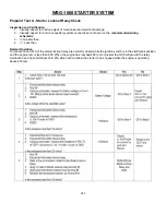
DIAGNOSIS AND TESTING
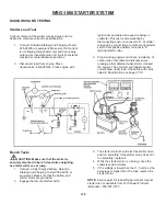
Starter Load Test
Conduct this test if the starter cranks slowly and it is
desired to compare current to specifications.
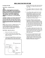
1. Connect Rotunda Starting and Charging Tester
078-00005 or equivalent. Make sure that current
is not flowing through ammeter and heavy-duty
carbon pile rheostat portion of circuit (rheostat at
maximum counterclockwise position).
2. Disconnect load from engine. Place
transmission in NEUTRAL. Crank engine with
ignition off, and determine exact reading on
voltmeter. This test is accomplished by
disconnecting push-on connector “S’’ at starter
relay and by connecting a remote control starter
switch from positive battery terminal to “S’’
terminal starter relay.
3. Stop cranking engine and reduce resistance of
carbon pile until voltmeter indicates same
reading as that obtained while starter cranked
the engine. The ammeter will indicate starter
current draw under load. Check this with value
listed in Specifications on page 07-19.
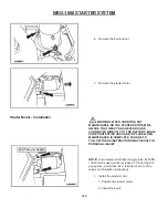
Bench Tests
CAUTION: Make sure that the starter is
securely mounted in bench vise while energizing,
as starter will move or jump.
1. Connect a fully charged battery, Rotunda
Starting and Charging Tester 078-00005, or
equivalent. Make sure that the battery and
starter motor are grounded.
2. Engage the remote starter switch.
3. The starter motor should eject the starter drive
and run smoothly. If the starter motor does not
run smoothly, replace it.
4. While the starter motor is running, check the
voltmeter and ammeter.
5. If the voltage is lower than the 11.0 volts, or the
amperage is higher than 70 amps, replace the
starter
motor.
NOTE:
Service parts for rebuilding permanent magnet
starter are not available from Ford Power Products.
1
Rotunda 1-800-578-7375
Содержание WSG-1068
Страница 1: ...WSG 1068 6 8 LITER INDUSTRIAL ENGINE SERVICE MANUAL EDI 1050180 March 2009 ...
Страница 12: ...6 WSG 1068 GENERAL INFORMATION DIAGNOSIS AND TESTING Special Tools ...
Страница 14: ...8 WSG 1068 GENERAL INFORMATION Symptom Chart Condition Possible Source Action ...
Страница 15: ...9 WSG 1068 GENERAL INFORMATION ...
Страница 46: ...30 WSG 1068 ENGINE INDEX CONT Subject Page Specifications Torque Specifications General Specifications 171 171 ...
Страница 48: ...32 WSG 1068 ENGINE Module View ...
Страница 49: ...33 WSG 1068 ENGINE Engine Intake Components ...
Страница 50: ...34 WSG 1068 ENGINE ...
Страница 51: ...35 WSG 1068 ENGINE Low End Components ...
Страница 52: ...36 WSG 1068 ENGINE ...
Страница 53: ...37 WSG 1068 ENGINE Upper End Components ...
Страница 54: ...38 WSG 1068 ENGINE ...
Страница 55: ...39 WSG 1068 ENGINE Major Front End Components ...
Страница 56: ...40 WSG 1068 ENGINE DIAGNOSIS AND TESTING Refer to Section 01 for basic mechanical concerns ...
Страница 65: ...49 WSG 1068 ENGINE 4 Tighten the nuts and bolts in the sequence shown ...
Страница 68: ...52 WSG 1068 ENGINE 4 Tighten the bolts in the sequence shown 5 Reinstall the PCV valve ...
Страница 75: ...59 WSG 1068 ENGINE ...
Страница 87: ...71 WSG 1068 ENGINE Camshaft Assembly Timing Mark Alignment ...
Страница 88: ...72 WSG 1068 ENGINE Timing Chains Camshaft Gears and Crankshaft Gears Alignment ...
Страница 98: ...82 WSG 1068 ENGINE Exhaust Manifold RH Installation 1 Follow the removal procedure in reverse order ...
Страница 106: ...90 WSG 1068 ENGINE 5 Remove the flywheel inspection plate 6 Remove the bolts and partially lower the oil pan 6675 ...
Страница 120: ...104 WSG 1068 ENGINE Engine Disassembly 1 With the engine on the engine stand remove the engine wiring harness ...
Страница 129: ...113 WSG 1068 ENGINE 20 Remove the timing chain guides 6K297 Remove the bolts Remove the timing chain guides ...
Страница 137: ...121 WSG 1068 ENGINE 1 Remove the Camshaft Holding Tool from the camshaft 6250 ...
Страница 143: ...127 WSG 1068 ENGINE 10 Install the roller followers 11 Remove the Valve Spring Spacer ...
Страница 155: ...139 WSG 1068 ENGINE 35 Install the timing chain guides 6K297 ...
Страница 167: ...151 WSG 1068 ENGINE 68 Position the water pump pulley 8509 on the water pump and install the bolts ...
Страница 172: ...156 WSG 1068 ENGINE SPECIFICATIONS ...
Страница 173: ...157 WSG 1068 ENGINE ...
Страница 174: ...158 WSG 1068 ENGINE ...
Страница 180: ...164 WSG 1068 IGNITION SYSTEM ...
Страница 188: ...172 WSG 1068 IGNITION SYSTEM Firing Order ...
Страница 190: ...174 WSG 1068 IGNITION SYSTEM Harness Connector Pinout Description I O Input Output ...
Страница 194: ...178 WSG 1068 IGNITION SYSTEM Engine Controls ...
Страница 195: ...179 WSG 1068 IGNITION SYSTEM Engine Sensors part of SK2U1L 12A200 BA ...
Страница 197: ...181 WSG 1068 IGNITION SYSTEM 90 Pin GCP Connector ...
Страница 199: ...183 WSG 1068 IGNITION SYSTEM ...
Страница 204: ...188 WSG 1068 FUEL SYSTEM ...
Страница 206: ...190 WSG 1068 COOLING SYSTEM INDEX CONT Subject Specifications General Specifications Torque Specifications Page 234 234 ...
Страница 225: ...209 WSG 1068 COOLING SYSTEM CHT Sensor Data Temperature Sensor Characteristics ...
Страница 229: ...213 WSG 1068 COOLING SYSTEM PINPOINT TEST A LOSS OF COOLANT ...
Страница 230: ...214 WSG 1068 COOLING SYSTEM PINPOINT TEST A LOSS OF COOLANT Continued ...
Страница 231: ...215 WSG 1068 COOLING SYSTEM PINPOINT TEST A LOSS OF COOLANT Continued PINPOINT TEST B THE ENGINE OVERHEATS ...
Страница 232: ...216 WSG 1068 COOLING SYSTEM PINPOINT TEST B THE ENGINE OVERHEATS Continued ...
Страница 233: ...217 WSG 1068 COOLING SYSTEM ...
Страница 234: ...218 PINPOINT TEST B THE ENGINE OVERHEATS Continued WSG 1068 COOLING SYSTEM ...
Страница 235: ...219 PINPOINT TEST C THE ENGINE DOES NOT REACH NORMAL OPERATING TEMPERATURE WSG 1068 COOLING SYSTEM ...
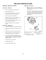
Страница 239: ...223 WSG 1068 CHARGING SYSTEM DIAGNOSIS AND TESTING Recommended Accessory Wiring ...
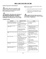
Страница 243: ...227 WSG 1068 CHARGING SYSTEM Symptom Chart ...
Страница 245: ...229 WSG 1068 CHARGING SYSTEM ...
Страница 250: ...234 WSG 1068 CHARGING SYSTEM SPECIFICATIONS Torque Specifications Generator Parts Cross Reference Special Tools ...
Страница 259: ...243 WSG 1068 STARTER SYSTEM ...
Страница 278: ...262 WSG 1068 ENGINE CONTROLS Diagrams and Schematics Symbols ...
Страница 279: ...263 WSG 1068 ENGINE CONTROLS GCP Power Distribution Box ...
Страница 281: ...265 WSG 1068 ENGINE CONTROLS Power Distribution ...
Страница 282: ...266 WSG 1068 ENGINE CONTROLS Ignition System ...
Страница 283: ...267 WSG 1068 ENGINE CONTROLS Starting System ...
Страница 284: ...268 WSG 1068 ENGINE CONTROLS Charging System ...
Страница 285: ...269 WSG 1068 ENGINE CONTROLS Engine Controls Sensors 1 of 2 ...
Страница 286: ...270 WSG 1068 ENGINE CONTROLS Engine Controls Sensors 2 of 2 ...
Страница 287: ...271 WSG 1068 ENGINE CONTROLS Fuel Injectors ...
Страница 288: ...272 WSG 1068 ENGINE CONTROLS Engine Controls Actuator Data Link Connector DLC WSG 1068 ENGINE CONTROLS ...
Страница 289: ...273 Engine Controls Dry Fuel EPR ...
Страница 290: ...274 WSG 1068 ENGINE CONTROLS Engine Component Locator View ...
Страница 305: ...289 WSG 1068 ENGINE CONTROLS Engine Performance While Under Load ...
Страница 306: ...290 WSG 1068 ENGINE CONTROLS Engine Concerns ...
Страница 315: ...299 WSG 1068 ENGINE CONTROLS SPECIFICATIONS ...
Страница 320: ...304 WSG 1068 METRICS ENGLISH METRIC CONVERSION ...
Страница 321: ...305 WSG 1068 METRICS DECIMAL AND METRIC EQUIVALENTS TORQUE CONVERSION ...
Страница 323: ...307 WSG 1068 METRICS ...
Страница 324: ...308 WSG 1068 METRICS ...
Страница 325: ...309 WSG 1068 METRICS ...
Страница 326: ...310 WSG 1068 METRICS ...
Страница 327: ...311 WSG 1068 METRICS ...
Страница 328: ...312 WSG 1068 METRICS ...
Страница 329: ...313 WSG 1068 METRICS ...
Страница 330: ...314 ...