Oil Heat – Eighteenth Edition – June 2015
6
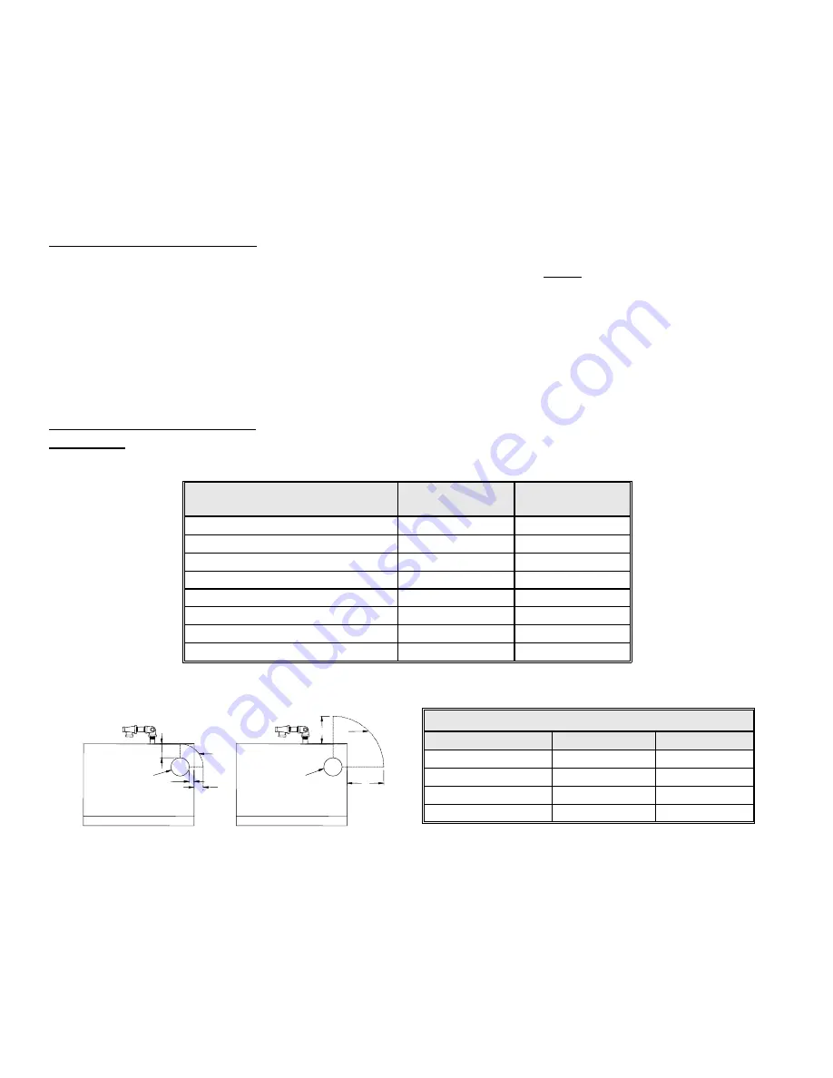
Figure 1A. Top View of Boiler -
Flue Connection Clearance to Combustibles
B
6"
(B) STANDARD VENT PIPE
TYPICAL FLUE
CONNECTION
8"
2"
1"
A
TYPICAL FLUE
CONNECTION
3"
(A) L-VENT OR PELLET VENT
6.
MONITOR RETURN TEMPERATURE:
The Manager continually senses the return temperature and will turn off the
zone outputs if the return temperature drops below 120
o
F (130
o
F if Option Switch #1 is ON). With the zone outputs
closed, the boiler water will quickly reheat and once the return temperature reaches 140
o
F (150
o
F if Option Switch
#1 is ON), then the Manager will reopen the zone valves.
7.
THERMOSTAT SATISFIED
: The thermostat light on the left side will go out. The burner light and the burner will then
turn off.
8.
ENERGY RECOVERY
: The circulator and zone valve remain energized. The circulating water will remove the energy
from the converter, sending the heat to the last zone that called. The energy recovery stage continues until the return
temperature has dropped sufficiently or until maximum timing has been reached. The boiler is now sitting cold,
waiting for the next call for heat. Maximum timing for heat recovery stage is usually set at twenty minutes for space
heating zones and is fixed at five minutes for the Hot Water zone.
(See Digital Manager Option Switch Settings)
.
RECEIVING and UNPACKING
Inspect shipment upon receipt for external damage. When unpacking and uncrating, inspect each item for internal
damage. Any damage found should immediately be reported to the freight carrier before installation. The receiver is
responsible for following the claims procedure of the freight carrier. The freight carrier is responsible for taking prompt
action on all claims. If freight cannot be inspected at the time of delivery, sign the bill of lading “Subject to Inspection” and
inspect the shipment as soon as possible after receipt. Replacements for parts damaged in shipment are available upon
receipt of a signed copy of a claim report
(concealed damage claims should be filed immediately against the freight carrier
by the consignee).
After unpacking, check each item against the packing list. Inspect it thoroughly for loose parts, instruction sheets and
packing lists. Immediately report any missing items. It is wise to complete the installation before discarding packing
material. Store all parts where they will not be damaged or lost during installation.
LOCATION and CLEARANCE
DANGER
:
Provide clearance to combustible surfaces in accordance with all local and national codes. Follow National
Fire Protection Association Bulletin NFPA Installation of Oil Burning Equipment and all applicable codes.
Installation Clearances from
Boiler Surfaces, Inches
Clearance to
Combustibles
Clearance for
Service
Front of boiler
15 1/2
20
Left side of boiler body
0
0
Right side of boiler body
0
0
Back of boiler body
4
4
Top of boiler body
16
16
Bottom of boiler legs to floor
0
9*
L-Vent: from flue pipe
3
3
Standard Flue: from flue pipe
9
9
* Minimum recommended clearance to allow door to fully open.
Boiler Weight and Water Content
Model
EK1 Frontier
EK2 Frontier
Weight
270 lbs
350 lbs
Water Content
2-1/2 gallons
4 gallons
Air Inlet Pipe Size
2"
3"
Boiler Flue Outlet
4"
6"


