background image

HYDRAULIC SYSTEMS AND CONNECTION DIAGRAMS

88

 smart Econ - emz-HCW - 180116

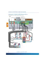
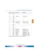
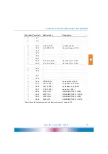
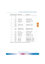
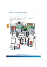
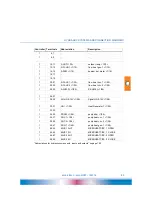
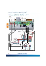
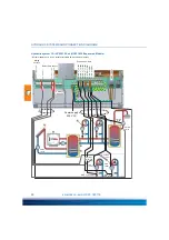
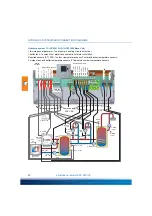
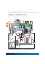
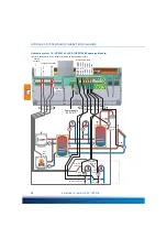
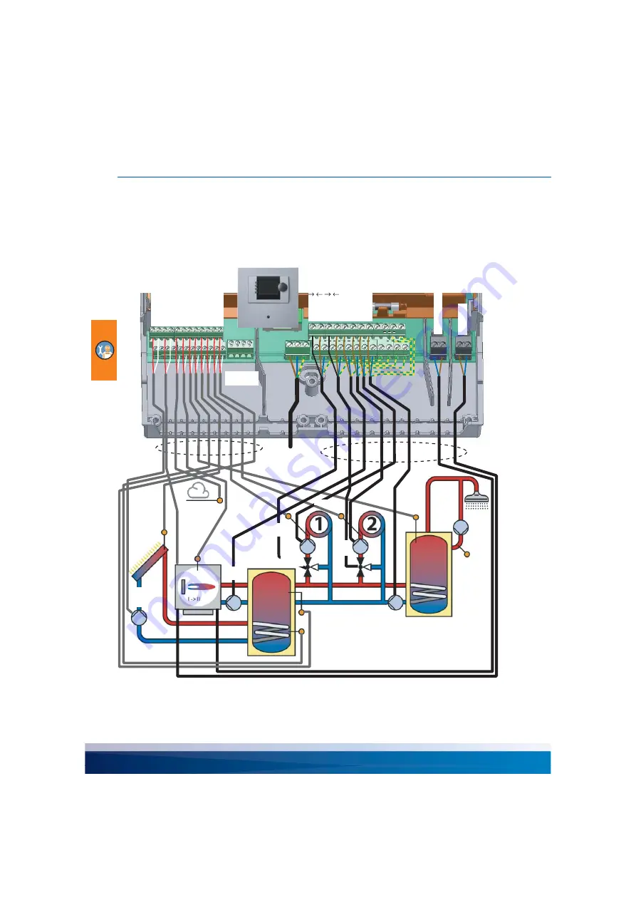
Hydraulic system 12: ›HCW 012 Sol‹ (HCW 1620 Base Unit)

1 two-stage heat generator, 4 heating circuits with mixer, 1 solar collector, 
1 buffer tank, 1 domestic hot water tank, domestic hot water circulation
Required sensors (PT 1000): 1 outdoor temperature sensor, 2 solar and boiler temperature sensors, 
3 storage tank and buffer temperature sensors, 5 flow/return contact temperature sensors

PE

PE

N

N

L

L

PE

PE

PE

PE

PE

PE

PE

PE

N

N

N

N

34

34

48

48

46

46

44

44

42

42

40

40

38

38

36

36

33

33

32

32

31

31

30

30

24

24

10

10

12

12

14

14

16

16

18

18

20

20

22

22

25

25

11

11

13

13

15

15

17

17

19

19

21

21

23

23

4

1

2 3

26

26

5

5

6

6

28

28

7

7

8

8

27

27

29

29

L

L

+

+

-

-

H

H

4

1

2 3

S-OUT <10>

S-LP-T <16>

S-DHW 

<14>

HG <30>

P-DHW <34>

P-CIRC 
<2/40>

S-FL-HG 
<12>

S-FL-HC 2 

<22>

M-HC 2 
<46,48>

P-HC 1 

<36>

P-HC 2 

<38>

S-CIRC 
<2/10>

AO-HG 
0-10V 
<28>

S-UP-T <24>

P-HG
<40>

PWM P-SOL <26>

A

O

-HG 0-10V <28>

S-OUT <10>

S-FL-HG <12>

S-DHW <14>

S-LP-T <16>

S-COL <18>

S-FL-HC 1 <20>

S-FL-HC 2 <22>

S-UP-T <24>

M-HC 2   <48>

M-HC 2   <46>

M-HC 1   <44>

M-HC 1   <42>

P-HG <40>

P-HC 2 <38>

P-HC 1 <36>

P-DHW <34>

STG_2 HG <32>

HG <30>

S-FL-HC 1 

<20>

M-HC 1 
<42,44>

STG_2 

HG <32>

S-COL

 <18>

P-SOL 

<2/32>

PWM 
P-SOL 
<26>

Power supply 

230 V AC

CAN bus 

Page 53

Temperature sensor

Pumps and mixers

Analog 

outputs

Содержание smart Econ HCW 1620

Страница 1: ...emz THE SMILING COMPANY HEATING SYSTEM CONTROLLER FOR HEAT GENERATION AND DISTRIBUTION OPERATING AND INSTALLATION INSTRUCTIONS...

Страница 2: ...nts and representations of these Operating and Installation Instructions are the intellectual property of emz Hanauer GmbH Co KGaA Unauthorized disclosure reproduction distribution or editing of this...

Страница 3: ...r heating system 12 smart Econ Transmission technology 12 Distance communication via the Internet 12 Remote maintenance via smart Econ Cloud 12 Cloud access 13 Information and control 13 Safety 13 Dat...

Страница 4: ...de OFF 29 Operating mode CHIMNEY SWEEP 29 TIMER PROGRAMS menu 30 Setting heating periods and temperatures 31 Selecting the day of the week 31 Setting times and temperatures 31 COPY DAY 31 COPY ALL VAL...

Страница 5: ...001 Sol HCW 810 58 Hydraulic system 2 HCW 002 SF HCW 810 60 Hydraulic system 3 HCW 003 HCW 810 62 Hydraulic system 4 HCW 004 Sol HCW 810 64 Hydraulic system 5 HCW 005 Sol HCW 810 66 Hydraulic system...

Страница 6: ...ht temperature 103 Frost protection 103 Summer operation 103 Domestic hot water temperature 103 Domestic hot water priority 104 Outdoor temperature controlled setting 104 Control loops with mixers 104...

Страница 7: ...4 DOMESTIC HOT WATER menu Installer 135 Setting the domestic hot water setpoint temperature Installer 136 Configure domestic hot water priority 137 Configuring the domestic hot water pump 137 Setting...

Страница 8: ...This symbol indicates sections with information on regular operation These sections contain descriptions of how to input individual settings on the controller These sections are aimed in particular at...

Страница 9: ...afety provisions Comply with all safety provi sions and contact a specialist in case of doubt Keep these assembly and operating instructions and all reference documents accessible at all times When re...

Страница 10: ...he heating system controller to an electri cal energy supply system in accordance with the technical data NOTE Make sure that only a dry or slightly moistened cloth is used for cleaning and servicing...

Страница 11: ...set as an additional reference variable by connecting the room controller To take solar radiation into account several room controllers can be attached e g to separate the heating circuits on the nort...

Страница 12: ...d to 63 C Solar heating system A configurable differential temperature control ensures that the solar heating system generates as much heat as possible You can load several heat consumers buffer boile...

Страница 13: ...and data archive are available for viewing In addition the various operating modes can be selected and indi vidual parameter values of the controller can be changed The recordings stored in the contro...

Страница 14: ...W smart Econ HCW 1620 Expansion module smart Econ HCW integrates the controller and the Userinterface into one compact housing for wall mounting Temperature sensors as well as pumps and valves are con...

Страница 15: ...SB interface inside the housing Micro USB B Installation and connection on page 45 smart Econ Room controller The smart Econ room controller determines the current room temperature The desired room te...

Страница 16: ...setting wheel to the end posi tion The connected heating circuit changes continuously to day mode until the setting wheel is reset To activate the setback function e g holiday turn the setting wheel...

Страница 17: ...g options of the function keys are shown on the display 5 Combined Turn push button with OK button function for menu navigation 6 Display You input settings and queries using the turn push button Sele...

Страница 18: ...ted components are displayed Example Press the rotary push button to access the menu Menu The menu shows the available options for displaying the controller s temperatures and operating statuses The s...

Страница 19: ...pective selectable option appears highlighted on the display Pressing the rotary push button OK confirms the selected menu item The respective submenu is opened or the corresponding selection is activ...

Страница 20: ...time is displayed in the setback and frost protection modes If the controller is not in day mode e g outside the programmed time period or if the operating mode does not permit day mode nothing appear...

Страница 21: ...tputs menu The Outputs menu displays the operating statuses ON OFF of the controlled controller outputs in the configured system The number after the output designations indicates the number of the sw...

Страница 22: ...s and calculated values that display the target state of the control loops Error messages In the event of a fault an alarm message appears on the display Information You can display further informatio...

Страница 23: ...on page 26 Depending on the access code the corresponding menu items appear Change values Select the value to be changed e g code or temperature by turning the rotary push button high lighted Press t...

Страница 24: ...DHCP IP Address OPERATING MODES AUTOMATIC CHIMNEYSWEEP TIMER PROGRAMS DOMESTIC HOT WATER Outputs Diagnostics BACK Enter Code INSTALLER COMMISSIONING OPERATING HOURS TEST HEIZKREIS n MENU Example LANGU...

Страница 25: ...ions in the menus Abbreviation Description ABS Anti blocking system CIRC Circulation DHW Domestic hot water FL Flow line HC Heat Circuit HG Heat generator HP Heat pump OT Outside temperature P Pump RC...

Страница 26: ...OPERATING MODES menu on page 27 TIMER PROGRAMS menu on page 30 HOLIDAY PERIODS menu on page 35 HEAT CIRCUITS menu on page 36 DOMESTIC HOT WATER menu on page 38 GENERAL menu on page 42 INTERNET menu o...

Страница 27: ...define the operating mode for the selected section of the system The following modes are possible Operating mode AUTOMATIC Operating mode DAY Operating mode NIGHT Operating mode FROST PROTECTION Oper...

Страница 28: ...y of a holiday period See HOLIDAY PERIODS menu on page 35 Operating mode FROST PROTECTION Time programs are not considered The temperature is always controlled to the frost protection room temperature...

Страница 29: ...n this operating mode all current temperatures and other input information are displayed but no switching functions are activated All components of the system must be switched to inactive Operating mo...

Страница 30: ...ample depending on the selected system In the TIMER PROGRAMS menu first select the heating circuit to which the setting is to apply Then select ROOM SETPOINTS TIMER PROGRAMS HEAT CIRCUIT 1 HEAT CIRCUI...

Страница 31: ...b to the left or right and press it to select a different day Setting times and temperatures Change values on page 23 COPY DAY With the turn knob select COPY DAY highlighted and press the turn knob A...

Страница 32: ...s Select HEAT CIRCUIT 2 press the turn knob COPY ALL VALUES press the turn knob select HEAT CIRCUIT 1 press the turn knob On the following pages you will find blank forms for rooms in which you can en...

Страница 33: ...es Room Day of the week Temperatures and periods C C C Monday Tuesday Wednesday Thursday Friday Saturday Sunday In between C setback temperature Room Day of the week Temperatures and periods C C C Mon...

Страница 34: ...es Room Day of the week Temperatures and periods C C C Monday Tuesday Wednesday Thursday Friday Saturday Sunday In between C setback temperature Room Day of the week Temperatures and periods C C C Mon...

Страница 35: ...than 10 holiday periods can be set for the entire system for a single heating circuit however only one On these holidays the room temperature is controlled to the frost protection room temperature Se...

Страница 36: ...point day room temperature for heating periods global eco temp C Global setpoint night room temperature for setback periods Select a heating circuit e g HEAT CIRCUIT 2 Make the settings for the other...

Страница 37: ...f necessary Change the setpoint temperature for this heating circuit if necessary Change values on page 23 For further settings see HEAT CIRCUITS menu Installer on page 130 SETTINGS ROOM1 NAME SETTING...

Страница 38: ...irculation times For further settings see DOMESTIC HOT WATER menu Installer on page 135 Setting the domestic hot water setpoint temperature Select SETTINGS in the DOMESTIC HOT WATER menu Change the de...

Страница 39: ...ou set the time from 00 00 to 00 00 the system will not be controlled at this time You can enter the times in steps of 1 minute the temperatures in steps of 1 10 degree Selecting the day of the week o...

Страница 40: ...Select the desired heating mode Setting circulation times To set the circulation times select TIMER CIRCULATION from the DOMESTIC HOT WATER menu You can change the circulation times via WEEKLY PROGRAM...

Страница 41: ...ge values on page 23 Select MAX RF TEMP CIRC in the DOMESTIC HOT WATER menu Change the limit value if necessary Maximum temperature in the return line of the circulation Temperature for stopping the c...

Страница 42: ...n page 23 Set date and time Select DATE TIME in the GENERAL menu Set the current date and time offset The time zone can be set here Change values on page 23 Note The date and time must be reset after...

Страница 43: ...can adjust the brightness of the LCD display and the volume of the buzzer display active intensity Brightness during operation display dimmed intensity Brightness in standby mode Beeper Level Alarm vo...

Страница 44: ...ork settings of the Userinterface Change values on page 23 For further settings see INTERNET menu Installer on page 143 INTERNET serial number 12345 CODE xxxxxxxxxxxxxxxxxxxx renew AUTH CODE NO delete...

Страница 45: ...nnect all poles of the power supply and secure them against being switched on again NOTE Externally secure the consumers that are connected to the potential free relay outputs according to their power...

Страница 46: ...ng If required you can alternatively use other temperature sensor versions outside sensor air duct sensor wall mounting room sensor flush mounting room sensor The temperature sensors are protected aga...

Страница 47: ...INSTALLATION AND CONNECTION smart Econ emz HCW 180116 47 smart Econ HCW Dimensions smart Econ HCW dimensions in millimeters 58 220 218 110 110 49 6 140...

Страница 48: ...ye level When used for temperature measurement The device must not be exposed to external heat Waste heat from electrical appliances waste heat from lighting heated walls via radiators etc 1 Release t...

Страница 49: ...g must not be operated Screw the shell to the intended installation site If necessary use dowels for wall mounting 1 Fasten the top securing screw so that a space of 2 to 3 mm is created between the w...

Страница 50: ...ic systems and connection diagrams on page 56 CAN bus Page 53 Fuse 6 3 A T Pumps or mixer 230 V AC 2 potential free relay outputs Power supply 230 V AC Temperature sensor Analog outputs Vortex sensor...

Страница 51: ...m controller housing First remove the hand wheel then remove the cover at each corner until the snap lock is unlocked To assemble proceed in reverse order Installation location room controller As a he...

Страница 52: ...mounting directly above an empty conduit is not recommended Room controller connection The smart Econ room controller is connected to the serial CAN bus If a room controller is the last device on a b...

Страница 53: ...d twisted pair can also be used 1 Vss 2 GND 3 H CAN High 4 L CAN Low Cable routing Lay the following cables 4 pole CAN bus line serial between smart Econ HCW and room controller with HCW 810 between b...

Страница 54: ...ermanently installed A jumper must be inserted on the last device of the CAN bus line It is irrelevant at which device the bus line ends Avoid junctions Example Tip Never connect more than two cables...

Страница 55: ...ia a router Prerequisites Available network connection establish one if necessary Working network structure Static IPv4 address in the home network or router with DHCP server usually included in stand...

Страница 56: ...ected system Example Hydraulic system 10 results from hydraulic system 8 HCW 008 Sol by deactivating the temperature sensor and the pump for the solar system In Curr System in the COMMISSIONING menu s...

Страница 57: ...ymbols Heat pump Solid fuel boilers Flow line Return line Mixer Heating circuit Domestic hot water Boiler e g fossil fueled Temperature sensor Outdoor temperature sensor Hot water storage tank with he...

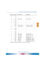
Страница 58: ...4 44 42 42 40 40 38 38 36 36 33 33 32 32 31 31 30 30 24 24 10 10 12 12 14 14 16 16 18 18 20 20 22 22 25 25 11 11 13 13 15 15 17 17 19 19 21 21 23 23 4 1 2 3 26 26 5 5 6 6 28 28 7 7 8 8 27 27 29 29 L L...

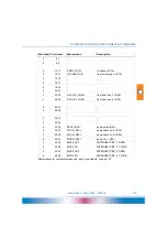
Страница 59: ...ollector temp 18 20 21 22 23 S FL HC 2 22 flow heat circ 2 22 24 25 S FL HC 3 24 flow heat circ 3 24 26 27 PWM P SOL 26 PWM pump solar 26 28 29 AO HG 0 10V 28 Signal HG 0 10V 28 30 31 HG 30 Heat Gener...

Страница 60: ...E PE PE PE PE N N N N 34 34 48 48 46 46 44 44 42 42 40 40 38 38 36 36 33 33 32 32 31 31 30 30 24 24 10 10 12 12 14 14 16 16 18 18 20 20 22 22 25 25 11 11 13 13 15 15 17 17 19 19 21 21 23 23 4 1 2 3 26...

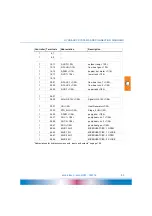
Страница 61: ...20 21 S FL SFB 20 flow sol fuel gen 20 22 23 S FL HC 2 22 flow heat circ 2 22 24 25 S FL HC 3 24 flow heat circ 3 24 26 27 28 29 AO HG 0 10V 28 Signal HG 0 10V 28 30 31 HG 30 Heat Generator 30 32 33 P...

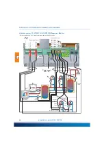
Страница 62: ...PE PE PE PE PE PE N N N N 34 34 48 48 46 46 44 44 42 42 40 40 38 38 36 36 33 33 32 32 31 31 30 30 24 24 10 10 12 12 14 14 16 16 18 18 20 20 22 22 25 25 11 11 13 13 15 15 17 17 19 19 21 21 23 23 4 1 2...

Страница 63: ...18 19 S CIRC 18 circulation 18 20 21 22 23 S FL HC 2 22 flow heat circ 2 22 24 25 S FL HC 3 24 flow heat circ 3 24 26 27 28 29 AO HG 0 10V 28 Signal HG 0 10V 28 30 31 HG 30 Heat Generator 30 32 33 P...

Страница 64: ...40 40 38 38 36 36 33 33 32 32 31 31 30 30 24 24 10 10 12 12 14 14 16 16 18 18 20 20 22 22 25 25 11 11 13 13 15 15 17 17 19 19 21 21 23 23 4 1 2 3 26 26 5 5 6 6 28 28 7 7 8 8 27 27 29 29 L L H H 4 1 2...

Страница 65: ...temp 18 20 21 S FL HC 1 20 flow heat circ 1 20 22 23 S FL HC 2 22 flow heat circ 2 22 24 25 S CIRC 24 circulation 24 26 27 PWM P SOL 26 PWM pump solar 26 28 29 AO HG 0 10V 28 Signal HG 0 10V 28 30 31...

Страница 66: ...38 38 36 36 33 33 32 32 31 31 30 30 24 24 10 10 12 12 14 14 16 16 18 18 20 20 22 22 25 25 11 11 13 13 15 15 17 17 19 19 21 21 23 23 4 1 2 3 26 26 5 5 6 6 28 28 7 7 8 8 27 27 29 29 L L H H 4 1 2 3 S OU...

Страница 67: ...temp 18 20 21 S FL HC 1 20 flow heat circ 1 20 22 23 S FL HC 2 22 flow heat circ 2 22 24 25 S UP T 24 upper tank 24 26 27 PWM P SOL 26 PWM pump solar 26 28 29 AO HG 0 10V 28 Signal HG 0 10V 28 30 31 H...

Страница 68: ...N 34 34 48 48 46 46 44 44 42 42 40 40 38 38 36 36 33 33 32 32 31 31 30 30 24 24 10 10 12 12 14 14 16 16 18 18 20 20 22 22 25 25 11 11 13 13 15 15 17 17 19 19 21 21 23 23 4 1 2 3 26 26 5 5 6 6 28 28 7...

Страница 69: ...pump 18 20 21 S FL HC 1 20 flow heat circ 1 20 22 23 S FL HC 2 22 flow heat circ 2 22 24 25 S MP T 24 middle tank 24 26 27 AO HG PWR 26 PWR signal HG 26 28 29 AO HG 0 10V 28 Signal HG 0 10V 28 30 31 H...

Страница 70: ...4 34 48 48 46 46 44 44 42 42 40 40 38 38 36 36 33 33 32 32 31 31 30 30 24 24 10 10 12 12 14 14 16 16 18 18 20 20 22 22 25 25 11 11 13 13 15 15 17 17 19 19 21 21 23 23 4 1 2 3 26 26 5 5 6 6 28 28 7 7 8...

Страница 71: ...S COL 18 collector temp 18 20 21 S FL SFB 20 flow sol fuel gen 20 22 23 S FL HC 2 22 flow heat circ 2 22 24 25 S UP T 24 upper tank 24 26 27 PWM P SOL 26 PWM pump solar 26 28 29 AO HG 0 10V 28 Signal...

Страница 72: ...44 42 42 40 40 38 38 36 36 33 33 32 32 31 31 30 30 24 24 10 10 12 12 14 14 16 16 18 18 20 20 22 22 25 25 11 11 13 13 15 15 17 17 19 19 21 21 23 23 4 1 2 3 26 26 5 5 6 6 28 28 7 7 8 8 27 27 29 29 L L...

Страница 73: ...collector temp 1 18 1 20 21 S FL HC 1 1 20 flow heat circ 1 1 20 1 22 23 S FL HC 2 1 22 flow heat circ 2 1 22 1 24 25 1 26 27 PWM P SOL 1 26 PWM pump solar 1 26 1 28 29 AO HG 0 10V 1 28 Signal HG 0 10...

Страница 74: ...4 24 10 10 12 12 14 14 16 16 18 18 20 20 22 22 25 25 11 11 13 13 15 15 17 17 19 19 21 21 23 23 4 1 2 3 26 26 5 5 6 6 28 28 7 7 8 8 27 27 29 29 L L H H 4 1 2 3 S CIRC 2 10 P CIRC 2 40 AO HG PWR 2 26 S...

Страница 75: ...2 18 19 2 20 21 2 22 23 S FL HC 3 2 22 flow heat circ 3 2 22 2 24 25 S FL HC 4 2 24 flow heat circ 4 2 24 2 26 27 2 28 29 2 30 31 2 32 33 2 34 35 P SOL 2 34 pump solar 2 34 2 36 37 P HC 3 2 36 pump he...

Страница 76: ...6 44 44 42 42 40 40 38 38 36 36 33 33 32 32 31 31 30 30 24 24 10 10 12 12 14 14 16 16 18 18 20 20 22 22 25 25 11 11 13 13 15 15 17 17 19 19 21 21 23 23 4 1 2 3 26 26 5 5 6 6 28 28 7 7 8 8 27 27 29 29...

Страница 77: ...1 S FL HC 1 1 20 flow heat circ 1 1 20 1 22 23 S FL HC 2 1 22 flow heat circ 2 1 22 1 24 25 S UP T 1 24 upper tank 1 24 1 26 27 1 28 29 AO HG 0 10V 1 28 Signal HG 0 10V 1 28 1 30 31 HG 1 30 Heat Gener...

Страница 78: ...6 18 18 20 20 22 22 25 25 11 11 13 13 15 15 17 17 19 19 21 21 23 23 4 1 2 3 26 26 5 5 6 6 28 28 7 7 8 8 27 27 29 29 L L H H 4 1 2 3 S FL SFB 2 12 P CIRC 2 40 S CIRC 2 10 P SFB 2 34 AO HG PWR 2 26 S CI...

Страница 79: ...2 14 15 2 16 17 2 18 19 2 20 21 2 22 23 S FL HC 3 2 22 flow heat circ 3 2 22 2 24 25 S FL HC 4 2 24 flow heat circ 4 2 24 2 26 27 2 28 29 2 30 31 2 32 33 2 34 35 P SFB 2 34 pump solid fuel 2 34 2 36 3...

Страница 80: ...N N L L PE PE PE PE PE PE PE PE N N N N 34 34 48 48 46 46 44 44 42 42 40 40 38 38 36 36 33 33 32 32 31 31 30 30 24 24 10 10 12 12 14 14 16 16 18 18 20 20 22 22 25 25 11 11 13 13 15 15 17 17 19 19 21 2...

Страница 81: ...8 19 1 20 21 S FL HC 1 1 20 flow heat circ 1 1 20 1 22 23 S FL HC 2 1 22 flow heat circ 2 1 22 1 24 25 1 26 27 PWM P SOL 1 26 PWM pump solar 1 26 1 28 29 AO HG 0 10V 1 28 Signal HG 0 10V 1 28 1 30 31...

Страница 82: ...31 30 30 24 24 10 10 12 12 14 14 16 16 18 18 20 20 22 22 25 25 11 11 13 13 15 15 17 17 19 19 21 21 23 23 4 1 2 3 26 26 5 5 6 6 28 28 7 7 8 8 27 27 29 29 L L H H 4 1 2 3 S CIRC 2 10 P CIRC 2 40 AO HG...

Страница 83: ...14 15 2 16 17 2 18 19 2 20 21 2 22 23 S FL HC 3 2 22 flow heat circ 3 2 22 2 24 25 S FL HC 4 2 24 flow heat circ 4 2 24 2 26 27 2 28 29 2 30 31 2 32 33 2 34 35 2 36 37 P HC 3 2 36 pump heat circ 3 2 3...

Страница 84: ...34 34 48 48 46 46 44 44 42 42 40 40 38 38 36 36 33 33 32 32 31 31 30 30 24 24 10 10 12 12 14 14 16 16 18 18 20 20 22 22 25 25 11 11 13 13 15 15 17 17 19 19 21 21 23 23 4 1 2 3 26 26 5 5 6 6 28 28 7 7...

Страница 85: ...S FL HC 1 1 20 flow heat circ 1 1 20 1 22 23 S FL HC 2 1 22 flow heat circ 2 1 22 1 24 25 S SUM FL 1 24 S SUM FL 1 24 1 26 27 1 28 29 AO HG 0 10V 1 28 Signal HG 0 10V 1 28 1 30 31 HG 1 1 30 Heat Gener...

Страница 86: ...11 13 13 15 15 17 17 19 19 21 21 23 23 4 1 2 3 26 26 5 5 6 6 28 28 7 7 8 8 27 27 29 29 L L H H 4 1 2 3 AO HG PWR 2 26 AO HG 0 10V 2 28 S CIRC 2 10 S FL HG 2 2 12 S FL HC 3 2 22 S FL HC 4 2 24 M HC 4...

Страница 87: ...2 23 S FL HC 3 2 22 flow heat circ 3 2 22 2 24 25 S FL HC 4 2 24 flow heat circ 4 2 24 2 26 27 2 28 29 AO HG 0 10V 2 28 Signal HG 0 10V 2 28 2 30 31 HG 2 2 30 Heat Generator 2 2 30 2 32 33 2 34 35 P H...

Страница 88: ...40 40 38 38 36 36 33 33 32 32 31 31 30 30 24 24 10 10 12 12 14 14 16 16 18 18 20 20 22 22 25 25 11 11 13 13 15 15 17 17 19 19 21 21 23 23 4 1 2 3 26 26 5 5 6 6 28 28 7 7 8 8 27 27 29 29 L L H H 4 1 2...

Страница 89: ...S FL HC 1 1 20 flow heat circ 1 1 20 1 22 23 S FL HC 2 1 22 flow heat circ 2 1 22 1 24 25 S UP T 1 24 upper tank 1 24 1 26 27 PWM P SOL 1 26 PWM pump solar 1 26 1 28 29 AO HG 0 10V 1 28 Signal HG 0 10...

Страница 90: ...2 12 14 14 16 16 18 18 20 20 22 22 25 25 11 11 13 13 15 15 17 17 19 19 21 21 23 23 4 1 2 3 26 26 5 5 6 6 28 28 7 7 8 8 27 27 29 29 L L H H 4 1 2 3 P CIRC 2 40 S CIRC 2 10 AO HG PWR 2 26 S CIRC 2 10 S...

Страница 91: ...2 18 19 2 20 21 2 22 23 S FL HC 3 2 22 flow heat circ 3 2 22 2 24 25 S FL HC 4 2 24 flow heat circ 4 2 24 2 26 27 2 28 29 2 30 31 2 32 33 2 34 35 P SOL 2 34 pump solar 2 34 2 36 37 P HC 3 2 36 pump he...

Страница 92: ...4 42 42 40 40 38 38 36 36 33 33 32 32 31 31 30 30 24 24 10 10 12 12 14 14 16 16 18 18 20 20 22 22 25 25 11 11 13 13 15 15 17 17 19 19 21 21 23 23 4 1 2 3 26 26 5 5 6 6 28 28 7 7 8 8 27 27 29 29 L L H...

Страница 93: ...1 S FL HC 1 1 20 flow heat circ 1 1 20 1 22 23 S FL HC 2 1 22 flow heat circ 2 1 22 1 24 25 S UP T 1 24 upper tank 1 24 1 26 27 1 28 29 AO HG 0 10V 1 28 Signal HG 0 10V 1 28 1 30 31 HG 1 30 Heat Gener...

Страница 94: ...18 20 20 22 22 25 25 11 11 13 13 15 15 17 17 19 19 21 21 23 23 4 1 2 3 26 26 5 5 6 6 28 28 7 7 8 8 27 27 29 29 L L H H 4 1 2 3 S FL HP 2 12 P CIRC 2 40 S CIRC 2 10 P HP 2 34 AO HG PWR 2 26 S CIRC 2 10...

Страница 95: ...7 2 18 19 2 20 21 2 22 23 S FL HC 3 2 22 flow heat circ 3 2 22 2 24 25 S FL HC 4 2 24 flow heat circ 4 2 24 2 26 27 2 28 29 2 30 31 HP 2 30 heat pump 2 30 2 32 33 2 34 35 P HP 2 2 34 pump heat pump 2...

Страница 96: ...48 48 46 46 44 44 42 42 40 40 38 38 36 36 33 33 32 32 31 31 30 30 24 24 10 10 12 12 14 14 16 16 18 18 20 20 22 22 25 25 11 11 13 13 15 15 17 17 19 19 21 21 23 23 4 1 2 3 26 26 5 5 6 6 28 28 7 7 8 8 2...

Страница 97: ...OL 1 18 collector temp 1 18 1 20 21 1 22 23 S FL HC 2 1 22 flow heat circ 2 1 22 1 24 25 S UP T 1 24 upper tank 1 24 1 26 27 PWM P SOL 1 26 PWM pump solar 1 26 1 28 29 AO HG 0 10V 1 28 Signal HG 0 10V...

Страница 98: ...16 16 18 18 20 20 22 22 25 25 11 11 13 13 15 15 17 17 19 19 21 21 23 23 4 1 2 3 26 26 5 5 6 6 28 28 7 7 8 8 27 27 29 29 L L H H 4 1 2 3 S FL SFB 2 12 P CIRC 2 40 S CIRC 2 10 AO HG PWR 26 S CIRC 2 10 S...

Страница 99: ...12 2 14 15 2 16 17 2 18 19 2 20 21 2 22 23 S FL HC 3 2 22 flow heat circ 3 2 22 2 24 25 S FL HC 4 2 24 flow heat circ 4 2 24 2 26 27 2 28 29 2 30 31 2 32 33 2 34 35 P SOL 2 34 pump solar 2 34 2 36 37...

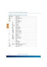
Страница 100: ...sensor HC Heating circuit FL Flow line RL Return line TOTAL Total flow LP Tank low level MP Tank middle level UP Tank upper level HW Hot water OUT Outside temperature CIRC Hot water circulation COL S...

Страница 101: ...falls below this limit again The storage tank temperature can increase further up to the storage tank safety temperature 90 C Storage recooling If the storage tank temperature is above the maximum sto...

Страница 102: ...K min The higher the temperature difference the faster the boiler is switched on This allows the heat generator to be switched on quickly in the event of large temperature differ ences and also avoid...

Страница 103: ...used for all heating circuits and time blocks In setback mode the temperatures can be set per room mixer circuit With the global night tempera ture the same temperature is used for all heating circuit...

Страница 104: ...ne sensor each for recording the current flow temperature Mixers allow much more precise temperature control than e g valves or the permanent switching on and off of the pumps The flow temperature req...

Страница 105: ...controllers can be configured as follows Outdoor temperature guided control without remote setting No room controller is installed in this variant The heating circuit runs in the AUTOMATIC operating m...

Страница 106: ...rature controlled flow temperature is influenced by the room temperature Devia tions of the room temperature from the setpoint temperature increase or decrease the flow tempera ture For setting see HE...

Страница 107: ...rface if necessary Set date and time on page 42 Enter the previously noted node numbers of all smart Econ room controllers Node number room controller on page 51 Configuring the room controller CONFIG...

Страница 108: ...below For settings that are also available for the end user see Settings during operation on page 23 Main menu for the installer Changing the Language LANGUAGE Change values on page 23 INSTALLER menu...

Страница 109: ...INSTALLER menu you can define settings for commissioning view the operating hours of the connected components and perform manual tests COMMISSIONING menu on page 110 OPERATING HOURS Menu on page 125 T...

Страница 110: ...e selected system In the COMMISSIONING menu you define the configuration for the entire system COMMISSIONING cur scheme HCW 001 Sol DATE TIME sw itch to summertime AUTO SETTINGS ZONES BASE OT HEAT CUR...

Страница 111: ...n the COMMISSIONING menu See also Set date and time on page 42 If necessary change the settings for daylight saving time Configuring heating circuits zones Select SETTINGS ZONE from the COMMISSIONING...

Страница 112: ...ature Display room temperature in overview mode without room controller pump continuously Outdoor temperature dependent pump operation pump on day ot C If the outdoor temperature in daytime operation...

Страница 113: ...Note Points P1 to P4 must follow each other in order and give a repetitively falling heating curve This means that P1 is at the lowest outdoor temperature P2 at the next higher P3 at the next P4 at t...

Страница 114: ...protector If this is not reached all pumps in the connected heating circuits also stop setting range 0 99 C maximum supply temp C Maximum boiler temperature setting range 0 99 C hysteresis K Boiler s...

Страница 115: ...from the COMMISSIONING menu Change the name of the heat pump if necessary Change other parameters if necessary minimum supply temp C The pump stops at temperatures below the set value startup pro tect...

Страница 116: ...for release of charge pump setting range 0 99 C hysteresis K Minimum temperature difference required between boiler and buffer to start the charge pump start up hysteresis Start of buffer charging bo...

Страница 117: ...r pump Boost of the current collector temperature above the current buffer temperature to start the solar pump Setting range 0 99 K storage max C Maximum permissible buffer temperature when solar pump...

Страница 118: ...nge 0 99 K storage max C Here Maximum temperature collector When cooling pump solar pump is exceeded OFF Setting range 0 99 K The storage tank recooling is controlled by the internal logic controllers...

Страница 119: ...s active every Monday from September to May Select SWITCH TO MANUAL AUTO in the TIMER ABS ON OFF menu Change the parameters if necessary In this menu the time switch and thus the anti lock circuit for...

Страница 120: ...for differential temperature of collector stor age tank Control variable for the modulation of the solar pump Factory settings 10 K adjustment range 0 25 K PUMP START SPEED limit value Solar pump sta...

Страница 121: ...tings 82 C setting range 0 90 C Change values on page 23 Sensor adjustment Select SENSOR ADJUSTING from the COMMISSIONING menu Menu page 1 example depending on the selected system Menu page 2 example...

Страница 122: ...rection 0 1 Temperature deviation from measured value 10K setting range 10 to 10 activated Enabling disabling the function in the system Factory settings YES setting range YES NO Note Only non critica...

Страница 123: ...it temp C Activate frost protection ot limit temperature C Outdoor temperature antifreeze threshold Configuring the room controller CONFIG RC Select CONFIG RC in the COMMISSIONING menu Example dependi...

Страница 124: ...heating circuit Node number room controller on page 51 Change values on page 23 NOTE Room temperature control for this heating circuit is active if the outdoor temperature control is deactivated When...

Страница 125: ...the individual components are displayed For example if the component has been replaced Select Srvc Hrs Reset OPERATING HOURS Heat Generator Heat Generator 1 Heat Generator 2 pump heat gen 1 pump heat...

Страница 126: ...menu on page 27 simulate operating states and set up the bus Note A simulation is only possible in OFF operating mode Test operation Select TRIAL RUN in the TEST menu TEST OPERATING MODES TRIAL RUN B...

Страница 127: ...ending on the selected system Select the desired temperature sensor and change the desired temperature if necessary First set the temperature sensor to be simulated to YES then set the desired value C...

Страница 128: ...ed temperature if necessary Change values on page 23 Simulate inputs Example depending on the selected system Select the desired input and change the desired value if necessary Change values on page 2...

Страница 129: ...116 129 Bus setup In the menu BUS SETUP you can deactivate or activate the CAN bus and check the bus compo nents CAN bus line on page 15 Note Bus setup can take some time BUS SETUP ENABLE BUS SETUP DI...

Страница 130: ...eco temp C offer the option of entering room setpoint temperatures centrally Provided that the use has been enabled for the respective heating circuit see the parameters use global day temp and use gl...

Страница 131: ...esis 0 1 Switching hysteresis for room temperature x 0 1 C Setting range 0 99 time lag 0 10 Inertia compensation advance heating time 0 direct ON OFF 3 delay for radiators 6 delay for underfloor heati...

Страница 132: ...0 C setting range 0 P3 P1 to P4 see BASE OT HEAT CURVE menu Change heating curve on page 113 Change values on page 23 Room temperature influence The flow temperature is adjusted according to the set p...

Страница 133: ...nfiguring the mixer control heating circuits with mixer For example select MIXER HEAT CIRC 2 in the HEAT CIRCUIT 2 menu Example depending on the selected system Note Mixer circuits are always preset f...

Страница 134: ...ing the heating pump For example select PUMP SETTINGS in the HEAT CIRCUIT 1 menu Example depending on the selected system Change the parameters if necessary Change values on page 23 PUMPSETTINGS stop...

Страница 135: ...7 Setting the domestic hot water heating times on page 39 Configuring the domestic hot water pump on page 137 Setting circulation times Installer on page 138 Configuring the circulation pump on page 1...

Страница 136: ...as the domestic hot water sensor value falls below the setpoint by the hysteresis It is switched off as soon as the setpoint is reached Change values on page 23 Activate or deactivate legionellae If...

Страница 137: ...mit value if necessary 1 0 Priority active 0 0 Priority disabled Change values on page 23 Configuring the domestic hot water pump Select SETTINGS PUMP DHW from the DOMESTIC HOT WATER menu Change the p...

Страница 138: ...hot water heating times on page 39 To control the circulation manually select SWITCH TO MANUAL AUTO in the same way as Manual control of domestic hot water heating on page 40 Configuring the circulat...

Страница 139: ...23 Select MAX RF TEMP CIRC in the DOMESTIC HOT WATER menu Change the limit value if necessary Maximum temperature in the return line of the circulation Temperature is reached circulation stops Factory...

Страница 140: ...and check the bus structure Bus setup on page 129 Select REGULATOR in the GENERAL menu NOTE The temperature sensor for the return line of the circulation must not be heated up by the storage tank Ins...

Страница 141: ...DEVICE CONFIGURATION smart Econ emz HCW 180116 141 HCW 810 Select REGULATOR HCW 1620 Select REGULATOR 1 or REGULATOR 2 REGULATOR REGULATOR BACK i REGULATOR REGULATOR 1 REGULATOR 2 BACK i...

Страница 142: ...DEVICE CONFIGURATION 142 smart Econ emz HCW 180116 The serial number of the controller is displayed here Example REGULATOR REGULATOR 1 serial number 85050 BACK i...

Страница 143: ...gs are configured correctly DHCP activated or correct IP address etc entered The status line of the display shows Server online To create a login the user requires appropriate authentication data usin...

Страница 144: ...authentication code via renew AUTH CODE This makes it impossible for people without access to the system to generate a new user on the sys tem or to log in via Auth code However existing users still r...

Страница 145: ...ight x depth 220 mm x 217 mm x 59 mm smart Econ Room controller Range of application for wall mounting Ambient temperature range 5 C to 40 C rel Humidity without temperature change 10 to 90 Electrical...

Страница 146: ...curve and resistance values of PT1000 temperature sensors 40 C 0 85 k 0 C 1 00 k 40 C 1 15 k 90 C 1 35 k 30 C 0 88 k 5 C 1 02 k 50 C 1 19 k 100 C 1 39 k 20 C 0 92 k 10 C 1 04 k 60 C 1 23 k 110 C 1 42...

Страница 147: ...f the power supply reliably and make sure they are not switched on again DANGER Loose cables Danger of death by electrocution When removing the heating system controller insulate all stripped cable en...

Страница 148: ...nued use of the heating system controller despite an obvious defect The use of spare parts and accessories that have not been approved by the manufacturer Applications exceeding the intended use Inapp...

Страница 149: ...ts and outputs 100 in menus 25 ABS 101 Access code entering 23 Air source heat pump 102 Anti legionella function 12 Antilock circuit 101 B Boiler 57 Brightness Display 43 Buffer management 101 Bus set...

Страница 150: ...35 manual control 40 priority 104 setpoint temperature 38 136 temperature 103 E Enter access code installer 108 Error messages 22 Expansion module 14 Exposure to sunlight 11 F Flow line 57 Flow temper...

Страница 151: ...modes 27 Operation prompts 18 settings 23 smartEcon HM user interface 17 smartEcon Room controller 16 Outdoor temperature sensor 57 Outdoor temperature controlled room heating 11 Outdoor temperature c...

Страница 152: ...on 48 Interfaces 15 open housing 48 technical data 145 smartEcon HM user interface operation 17 smartEcon room controller 15 operation 16 technical data 145 smartEcon temperature sensor 46 characteris...

Страница 153: ...INDEX smart Econ emz HCW 180116 153...

Страница 154: ...Edition EN 03 2018 emz HCW 180116 emz Hanauer GmbH Co KGaA Siemensstra e 1 92507 Nabburg Germany Phone 49 0 9433 898 0 info emz hanauer com Fax 49 0 9433 898 188 www emz hanauer com...

Отзывы: