AMETEK CTS
BS 200N100
Operating manual
V 1.12
14 / 21
7.
Application
7.1.
Test setup ISO 7637-2 Ed.3 (2011)
Important
- The artificial network AN shall be connected directly to the ground reference plane.
- All wires between AN and the DUT shall be isolated from the ground plane by 50mm.
- The DUT will be placed on the ground plane as in real installation.
- directly grounded to the ground plane or
- 50mm isolated from the ground plane
- The position of the instruments shall be as specified in the standard.
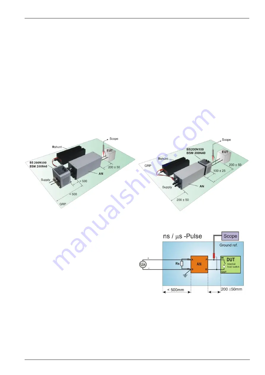
Switch as per ISO 7637-2:2011
For the measurement of the emission the ISO 7637-2: 2011 standard defines two different switches and switch
positions. These are pending from the rise time of the voltage impulse. The switch position for slow impulses in
the ms range is before the electrical switch see figure 7.1. For fast impulses, in
s and ns range, the switch is on
the DUT side figure 7.2. During the examination, only one switch may be operated.
For the emission measurement ISO 7637-2: 2011 defines the test setup below. EM Test propose the test setup
illustrated in figure 7.1, 7.2 and 7.3.
Figure 7.1.: Setup for pulses in the ms range
Figure 7.2.: Setup for pulses in the
s / ns range
Setup for DUT with internal Switch
ISO 7637-2:2011 offers a new test setup as shown in
figure 7.3 for measuring the transient emission using
DUT with internal switch.
This setup is for measuring the transient emission
pulses in ns to us range. Cause the existing original
switch inside the DUT, it is not necessary to use the
BS200N100 in the setup. The shunt resistor Rs is to
use as per clause 5.2 of the ISO 7637-2 standard.
Figure 7.3: Setup for DUT with internal switch for
s / ns pulses


