AMETEK CTS
BS 200N100
Operating manual
V 1.12
7 / 21
3.
Equipment description
The Switch BS 200N100 is designed with the following main components:
- Electronic switch
- Differential Voltage divider 200:1
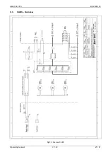
Figure 3.1. : General diagram BS 200N100
3.1.
Electronic switch
The electronic Switch has 2 operating modes:
NC
: Normally Closed
NO
: Normally Open
Figure 3.2 shows the both operating modes with the
variable parameters “Repetition“ and “Duration“
The electronic switch disconnects the DUT from battery
supply voltage for a specified time in a well specified and
reproducible manner.
Figure 3.2. : Operating modes Switch BS 200N100
The electronic switch is activated by pushing the button
TEST
. The red LED indicates the closed status.
In
AUTO
mode the electronic switch is triggered internally with the preselected repetition rate. In MANUAL mode a
single switching event is triggered either by pushing the
MANUAL
button or by remote trigger.
The electronic switch can switch currents up to 100A and is able to withstand voltages up to 1000V.
The electronic switch is protected against overload and can withstand short-circuit conditions.
Specific protection requirements of the EUT must be separately assured by the user.
Inrush currents
Inrush currents up to 500A are permitted.
Overvoltage
The switch is protected against over voltages higher than 1000V by internal varistors.
3.2.
Divider 1:200
The built in differential divider is designed to monitor the supply voltage. The measuring signal is available on the
MONITOR
BNC plug. The 10MHz bandwidth is not designed for measuring the transient emission. The standard
recommends an external voltage probe for this measurement.
The divider is an ohmic- capacitive differential divider with a 50
terminating resistor to the BNC plug.
3.3.
Air cooling
The BS200N100 has internal air ventilation for cooling the battery supply switch. Ventilation grid and
ventilator (blower) must be kept away from other devices in order to allow sufficient air flow through the
battery supply switch.


