background image

12433-10-0109

Page 11

1.  

STOP!

   Read the safety information above.

2.  Set the thermostat to lowest setting.

3.  Turn  off  all  electric  power  to  the  appliance    (if  appli

-

cable).

4.   Remove control access panel (front panel).

5.   Push in gas control knob slightly and turn clockwise                      


 to "OFF".


NOTE:  Knob cannot be turned from "PILOT" to "OFF" 

unless knob is pushed in slightly.  Do not force.

6.   Wait ten (10) minutes   to clear out any gas.  Then smell 

for gas, including near the floor.  If you smell gas, STOP! 

Follow "B" in the safety information above.  If you don't 

smell gas, go to the next step.

7.   Remove the pilot access cover located on the combustion 

chamber.  

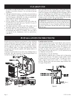
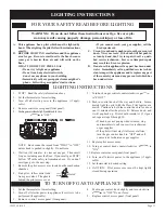
8.   Find pilot - follow metal tube 


from gas control.  The pilot is 


behind the pilot access cover.

9.   Turn knob on gas control counterclockwise 


to "PILOT."

10.  Push in control knob all the way and hold in.  Imme-

diately light the pilot with the Piezo Pilot Ignitor or a 

match.  Continue to hold the control knob in for about 

one (1) minute after the pilot is lit.  Release knob,  and 

it will pop back up.  Pilot should remain lit.  If it goes 

out, repeat steps 5 through 10.

  • If knob does not pop up when released, stop 

and immediately call your service technician 

or gas supplier.  

  • If the pilot will not stay lit after several tries, 

turn the gas control knob to "OFF" and call 

your service technician or gas supplier.  

11.  Replace pilot access cover.
12.  Turn gas control knob counterclockwise  

 to 

"ON."

13. Replace control access panel (front panel).
14.  Turn  on  all  electric  power  to  the  appliance  (if  appli

-

cable).

15.  Set thermostat to desired setting.

16.  CAUTION:    Pilot  access  cover  must  be  kept  tightly 

closed during operation.

TO TURN OFF GAS TO APPLIANCE

FOR YOUR SAFETY READ BEFORE LIGHTING

WarninG:

  If you do not follow these instructions exactly, a fire or explo

-

sion may result causing property damage, personal injury or loss of life.

a.   this appliance has a pilot which must be lighted by 

hand.  When lighting the pilot, follow these instructions 

exactly.

B.   BeFore liGHtinG  smell all around the appliance 

area for gas.  Be sure to smell next to the floor because 

some  gas  is  heavier  than  air  and  will  settle  on  the 

floor.


WHat to Do iF You sMell Gas

• Do not try to light any appliance.

• Do not touch any electrical switch; 

  do not use any phone in your building.

• Immediately call your gas supplier from a neighbor's 

phone.  Follow the gas supplier's instructions.

• If you cannot reach your gas supplier, call the 

fire department.

c.   use only your hand to push in or turn the gas control 

knob.  never use tools.  if the knob will not push in 

or turn by hand, don't try to repair it; call  a  quali

-

fied service technician.  Force or attempted repair 

may result in a fire or explosion.

D.   Do not use this appliance if any part has been under 

water.  Immediately call a qualified service techni

-

cian to inspect the appliance and to replace any part 

of the control system and any gas control which has 

been under water.

LIGHTING INSTRUCTIONS

1.   Set the thermostat to lowest setting.

2.   Turn off all electric power to appliance if service is to be 

performed (if applicable).

3.   Remove  control  access panel  (front panel).

4.   Push in gas control  knob slightly and turn clockwise  

  to "OFF." Do not force.

5.   Replace control  access panel  (front panel).

PILOT

BURNER

THERMOPILE

liGHtinG instructions

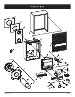
Содержание DV-210-SG

Страница 1: ...th or serious illness Installer Leave this manual with the appli ance Consumer Retain this manual for future refer ence Do not store or use gasoline or other flamma ble vapors and liquids in the vicin...

Страница 2: ...ifications 6 Gas Supply 7 Clearances 8 Installation Instructions 8 9 Thermostat Location 10 Lighting Instructions 11 Pilot Flame Characteristics 12 Main Burner Flame Characteristics 12 Maintenance 12...

Страница 3: ...ied service person More frequent cleaning may be required due to excessive lint from carpeting bedding materials etc It is impera tive that control compartments burners and circulating air passageways...

Страница 4: ...g vehicle trailer or area Finally let the service man and firefighters check for escaped gas Have them air out the area before you return Properly trained LP Gas service people should repair the leak...

Страница 5: ...uiredinaccordance with the above provisions shall comply with NFPA 720 and be ANSI UL 2034 listed and IAS certified 3 SIGNAGE Ametalorplasticidentificationplateshallbe permanently mounted to the exter...

Страница 6: ...erformed only by a qualified agency The term qualified agency meansanyindividual firm corporationorcompanywhicheitherin person or through a representative is engaged in and is responsible for a the in...

Страница 7: ...that a drip line be installed near the gas inlet This should consist of a vertical length of pipe tee connected into the gas line that is capped on the bottom in which condensation and foreign partic...

Страница 8: ...nimum wall depth is 4 1 2 114mm and maximum wall depth is 13 330mm The use of tubes not supplied by the manufacturer result in unsatisfactory performance The furnace is to be located on an outside wal...

Страница 9: ...l Remove 5 127mm diameter air inlet tube from collar of air drop assembly 2 Attach3 76mm diameterflueoutlettubeontoflueoutletcollar oncombustionchamber Besure3 76mm diameterflueoutlet tube is placed a...

Страница 10: ...d be Across the thermopile terminals 400 450 millivolts with ther mostat off Across the thermopile terminals 150 250 millivolts with ther mostat on Across the thermostat wires at the valve less than 3...

Страница 11: ...to desired setting 16 CAUTION Pilot access cover must be kept tightly closed during operation To Turn Off Gas To Appliance FOR YOUR SAFETY READ BEFORE LIGHTING Warning If you do not follow these inst...

Страница 12: ...ted After this the valve and orifice elbow can be removed as a unit Cleaning The Pilot Burner Cleaning of the pilot may be an annual necessity due to spiders After removing the supply tubing and orifi...

Страница 13: ...properly size orifice 4 Pilot and main burner go out during normal operation a Check millivolts b Check for proper size of pilot flame c Check for defective or weak thermopile d Check input reduce as...

Страница 14: ...HOLE 11 852098 NUT FOR ORIFICE FITTING 12 742134 BURNER ORIFICE DV 210 NAT 12 742133 BURNER ORIFICE DV 215 NAT 12 742297 BURNER ORIFICE DV 210 LPG 12 742282 BURNER ORIFICE DV 215 LPG 13 742038 ORIFICE...

Страница 15: ...12433 10 0109 Page 15 PARTS VIEW...

Страница 16: ...appliance is equipped with a three prong grounding plug for your protection against shock hazard and should be plugged directly into a properly grounded three prong re ceptacle Do not cut or remove th...

Страница 17: ...ms Empire Comfort Systems Inc 918 Freeburg Ave Belleville IL 62220 If you have a general question about our products please e mail us at info empirecomfort com If you have a service or repair question...

Отзывы: