CG Drives & Automation, 01-6142-01r0
Control Connections
31
4.3
Inputs configuration
with the switches
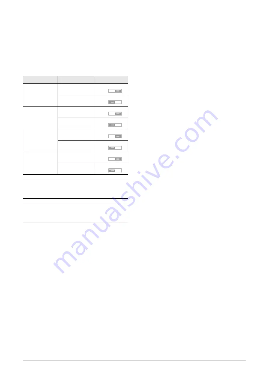
The switches S1 to S4 are used to set the input configuration
for the 4 analogue inputs AnIn1, AnIn2, AnIn3 and AnIn4
as described in table 18. See Fig. 37 for the location of the
switches.
4.4
Connect control cables
Here you will make up the minimum wiring for starting.
To comply with the EMC standard, use screened control
cables with plaited flexible wire up to 1.5 mm2 (AWG15) or
solid wire up to 2.5 mm2(AWG13). We recommend using
twisted pair cables between Master and follower for commu-
nication signals.
1. Connect a level sensor between terminals 1 (+10 VDC)
and 2 (AnIn 1) as in Fig. 38 The default setting for the
AnIn1 is 4-20 mA. If the level sensor has a 0-10 V inter-
face, change the position of switch (S1) on control board
(chapter 4.3 page 35).
2. Connect an external Auto run switch between terminal
11 (+24 VDC) and 8 (DigIn1, Flow Auto) as in Fig. 38.
Set the switch in the open position (digital input set to
low state). (Do not activate the signal at this point.)
3. Connect an external Full speed switch between terminal
11 (+24 VDC) and 9 (DigIn2, Flow Run) as in Fig. 38.
Set the switch in the open position (digital input set to
low state). (Do not activate the signal at this point.)
4. Connect a communication cable between Master
terminal 10 (DigIn3) and Follower terminal 21
(DigOut2) as in Fig. 38. (Only if Master/Follower).
5. Connect a communication cable between Master
terminal 21 (DigOut2) and Follower terminal 10
(DigIn3) as in Fig. 38. (Only if Master/Follower).
6. Connect an overflow level switch (optional) between
terminal 11 (+24 VDC) and 18 (DigIn6, Lvl Overflow)
as in Fig. 38 Connect the signal to the Follower drive
instead in a Master-Follower configuration for
redundancy.
Table 18
Switch settings
Input
Signal type
Switch
AnIn1
Voltage
S1
Current (default) S1
AnIn2
Voltage
S2
Current (default) S2
AnIn3
Voltage
S3
Current (default) S3
AnIn4
Voltage
S4
Current (default) S4
NOTE: Scaling and offset of AnIn1 - AnIn4 can be
configured using the software. See menus [512], [515],
[518] and [51B] in section 10.5, page 138.
NOTE: the 2 analogue outputs AnOut 1 and AnOut 2 can
be configured using the software. See menu [530]
section 10.5.3, page 148
U
I
U
I
U
I
U
I
U
I
U
I
U
I
U
I


