background image

TB-6584

 Page 10 of 13

© 2016 DESCO INDUSTRIES, INC.

Employee Owned

Relay Terminal

The SmartLog V5™ features a relay terminal that can be 

integrated with electronic door locks, lights, buzzers, etc.
Contact Rating: 

1A @ 30VDC, .5A @ 125VAC

Maximum Switching Power:  30W

Maximum Switching Voltage:  250VAC, 220VDC

Maximum Switching Current:  1A

BELL

BUZZER

DOOR LOCK

LIGHT

OTHER

POWER

SOURCE

0 - 250VAC

0 - 220VDC

HOT

NORMALLY

OPEN

COMMON / NEUTRAL

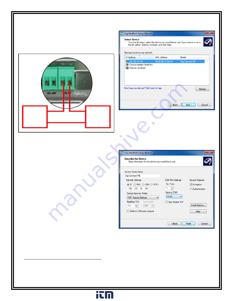
Figure 16.  Relay installation

The relay close (activation) time may be modified using the 

TEAM5 Software.  

Ethernet Setup

The SmartLog V5™ provides the option to connect to a PC 

either directly or remotely via a LAN setup.  The following 

procedure will outline how to connect your SmartLog V5™ 

to a network using its embedded Ethernet communication 

module.  This is the recommended method of installation.
Should this method not be ideal for your setup, see “Direct 

Connection to a PC” in the following section for an alternate 

way to establish communication to your SmartLog V5™.
1.  Take note of the MAC address of your SmartLog V5™.  

  This can be found on a label located at the bottom and 

  right-hand side of the unit
2.  Verify that the Ethernet cable is securely connected to 

  your network and SmartLog V5™.  The SmartLog V5™  

     must be powered during Ethernet setup.  The LEDs on 

     the Ethernet port will illuminate when a connection to the 

  network is established.
3.  Use the following link to download the necessary drivers 

  for the Ethernet module.  It is compatible with Windows 

  Server 2003, Server 2008, XP, Vista and 7.

  http://ftp1.digi.com/support/driver/40002549_E.zip

4.  Unzip the downloaded file and open the folder.  Run 

  “Setup32.exe” if using a 32-bit machine or “Setup64.exe” 

  if using a 64-bit machine.

6.  You will next be prompted to enter the device settings.  

  You may choose to simply accept the default settings.  

  Take note of the assigned COM Port number.  This value 

  will be needed when building the communication settings 

  in the TEAM5 Software.  Click the Finish button when 

 complete.

Figure 17.  Selecting the MAC address

Figure 18.  Ethernet device settings

5.


The Digi RealPort Setup Wizard window will open.  


Select the proper MAC address and click the Next button.

www.

.com

[email protected]

1.800.561.8187

Содержание SmartLog V5

Страница 1: ...mits the SmartLog will indicate failure via audio and visual alarms Use the included relay terminal to promote access control for passed tests The SmartLog V5 can also be networked to a company s Intranet using its embedded Ethernet module The SmartLog V5 is calibrated to NIST traceable standards ESD Association Information Compliance verification should be performed prior to each use daily shift ...

Страница 2: ...ing 5 Features and Components 6 Installation 6 Clock Configuration 6 Tester Configuration 7 Hardware Setup 8 50771 Turnstile Bracket 10 Relay Terminal 10 Ethernet Setup 11 Direct Connection to PC 11 TEAM5 Software 12 Operation 12 Calibration 13 Specifications 13 Limited Warranty www com information itm com 1 800 561 8187 ...

Страница 3: ...tLog V5 PC with TEAM5 Software Supervisor Department Manager Department Manager Department Manager Illustration of the SmartLog V5 System collecting and transferring ESD data to a central PC where it is distributed to supervisors and department managers www com information itm com 1 800 561 8187 ...

Страница 4: ...V5 Turnstile 220VAC 50771 Turnstile Bracket SmartLog V5 50424 Limit Comparator for Testers Packaging SmartLog V5 Test System 1 SmartLog V5 1 Mounting Bracket 1 Dual Independent Foot Plate 1 Foot Plate Cable 6 1 Power Adapter 9VDC 1 25A center pos 1 Right Angle Ground Cord 2 Mounting Anchors 2 Mounting Screws 1 Thumb Screw 1 10mm Wrist Cord Adapter 50769 only 1 Certificate of Calibration See page 8...

Страница 5: ...er from the tester K Buzzer Volume Adjustment Turn the trimpot clockwise to increase the buzzer volume and counter clockwise to decrease the volume L Foot Plate Jack Connect one end of the foot plate cable here and the other end to the dual foot plate M Test Limit DIP Switch Use this DIP switch to configure the resistance limits of the tester See Tester Configuration on page 6 for more information...

Страница 6: ...owing configurations BAUD 9600 PARITY ODD SMART LOG ID 00 The SmartLog ID is a two digit field that ranges from 00 63 Each SmartLog must have a unique ID number should you have several units configured to your system DAYLIGHT DISABLE PORT EXPAND YES DECODE NO READER MAGSTRIPE 5 Press the MENU button to save and exit setup mode Tester Configuration The resistance limits for footwear and wrist strap...

Страница 7: ... LEDs continue to blink inspect the foot plate cable and verify that it is securely connected at both terminals Hardware Setup If the SmartLog V5 is located near a restroom sink or other water source operators will need to be instructed to thoroughly dry their hands before testing Wet hands may cause inaccurate test results and damage to the tester 1 Use the included screws and anchors to secure t...

Страница 8: ...thread 3 Washers 1 Nylon Bushing Installation 1 The 50771 Turnstile Bracket provides a way to route the SmartLog s cables through the turnstile s enclosure in order to eliminate tampering of the connections Use the drill pattern in Figure 9 to mill the top cover of your turnstile and clear space to mount the bracket Typ 120º 3X 189 R 90 875 Figure 9 Drill pattern for mounting the bracket to a turn...

Страница 9: ...slots on the back of the SmartLog V5 with the hooks on the turnstile bracket Figure 13 Locating the mounting hooks on the bracket 7 Slide the SmartLog V5 into the bracket from top to bottom Secure the SmartLog V5 to the bracket by fastening the included 4 40 screw on the left side of the tester Figure 14 Sliding the SmartLog V5 into the bracket and securing it into place with the 4 40 screw slide ...

Страница 10: ...ote of the MAC address of your SmartLog V5 This can be found on a label located at the bottom and right hand side of the unit 2 Verify that the Ethernet cable is securely connected to your network and SmartLog V5 The SmartLog V5 must be powered during Ethernet setup The LEDs on the Ethernet port will illuminate when a connection to the network is established 3 Use the following link to download th...

Страница 11: ...ton when complete Figure 21 Directly connecting the SmartLog V5 to a PC Non inverted RS 232 cable DB9 serial adapter PC with TEAM5 Software SmartLog V5 TEAM5 Software TEAM5 is the most powerful and accurate ESD Test Acquisition Software on the market When used with the EMIT SmartLog TEAM5 allows manufacturers and assemblers to automate the collection of employee ESD testing It has a set of robust ...

Страница 12: ...se pass When performing a wrist strap test be sure to completely plug in the wrist cord into the tester s jack 4 Press and hold the metal touch plate on the tester to perform the test Hold your finger on the touch plate until the results of the test are displayed If performing a wrist strap test and the wrist strap status LEDs do not illuminate verify that the wrist cord is correctly inserted into...

Страница 13: ... Voltage 5 VDC open circuit Wrist Strap and Footwear Test Voltage 30 VDC open circuit Test current is limited by resistors and varies on the test range setting 100 kilohms 1 gigohm Memory Capacity2 Test ID Length Test Transactions 4 16 100 5 15 300 6 14 600 7 14 000 8 13 400 9 12 900 10 12 400 11 11 900 12 11 500 13 11 100 14 10 700 15 10 400 16 10 100 2 This only applies should the SmartLog V5 lo...

Отзывы: