Functional Description
RTM-ATCA-F140 Installation and Use (6806800M97A
)
54
4.8.5
BCM84740 Control and Status
The RTM FPGA provides register access to the BCM84740 TXONOFF signal. This allows the PHY
to be placed into low-power mode also drives LPMODE to the QSFP+ site. According to the
QSFP+ spec, assertion of LPMODE may or may not cause the transmitter to be disabled. More
detail can be found in section 3.5.6. The RTM FGPA provides access to the LASI status signal of
the BCM84740. This signal can be programmed to cause an interrupt when its state changes.
4.8.6
Reset Handling
The RTM FPGA provides register control of the reset inputs to the BCM8727, BCM84754,
BCM84740, and the QSFP+ port. This allows the front blade control processor to reset the
PHYs and QSFP+. At system reset, as indicated by the zone 3 RTM_RST# signal, the PHYs and
QSFP+ are forced into reset until this is cleared by a register write. This is to ensure that the
PHYs are in reset until the telecom clock subsystem has been programmed if necessary to
provide the PHY reference clocks.
4.8.7
Synchronous Ethernet Clock Recovery
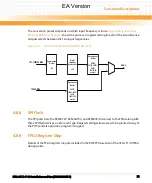
The BCM8727, BCM84754, and BCM84740 PHYs provide clocks recovered from the incoming
data stream of all of their ports. The frequency of these clocks is either 156.25MHz or
161.1328125MHz depending on whether the interface is operating at 1Gbps or 10Gbps
respectively. The RTM FPGA provides two identical blocks that each select between all of these
clock sources (ten total) and convert it to an 8kHz reference that is connected to the front blade
telecom clock subsystem.
EA Version
Содержание RTM-ATCA-F140
Страница 6: ...RTM ATCA F140 Installation and Use 6806800M97A Contents 6 Contents Contents EA Version ...
Страница 8: ...RTM ATCA F140 Installation and Use 6806800M97A 8 List of Tables EA Version ...
Страница 10: ...RTM ATCA F140 Installation and Use 6806800M97A 10 List of Figures EA Version ...
Страница 14: ...RTM ATCA F140 Installation and Use 6806800M97A About this Manual 14 About this Manual EA Version ...
Страница 20: ...Introduction RTM ATCA F140 Installation and Use 6806800M97A 20 EA Version ...
Страница 30: ...Hardware Preparation and Installation RTM ATCA F140 Installation and Use 6806800M97A 30 EA Version ...
Страница 34: ...Controls LEDs and Connectors RTM ATCA F140 Installation and Use 6806800M97A 34 EA Version ...
Страница 58: ...Functional Description RTM ATCA F140 Installation and Use 6806800M97A 58 EA Version ...
Страница 60: ...Related Documentation RTM ATCA F140 Installation and Use 6806800M97A 60 EA Version ...
Страница 70: ...Index RTM ATCA F140 Installation and Use 6806800M97A 70 EA Version ...
Страница 71: ...EA Version ...

