Functional Description
RTM-ATCA-F140 Installation and Use (6806800M97A)
51
4.7.2
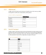
10MHz Input
An SMA connector is located on the front panel of the RTM-ATCA-F140 to receive a 10MHz
clock signal from a GPS receiver. Characteristics of this input are:
4.7.3
Time-Of-Day Input
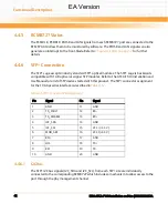
An RJ45 connector is provided on the front panel of the RTM-ATCA-F140 for reception of serial
RS-485/RS-422 time-of-day information from a GPS receiver. The serial format is 9600 baud,
8data bits, no parity, and 1 stop bit. There is also a 1PPS input channel on the RJ45 connector
for GPS receivers that transmit 1PPS serially. Below is the pinout of this port:
Table 4-12 10MHz Input Specifications
10MHz SMA Input
Waveform
Sine wave
Minimum
Amplitude
0.5Vp-p
Maximum
Amplitude
5.0Vp-p
Impedance
50 ohms
Termination
50 ohms
Table 4-13 Time-Of-Day RJ45 Pinout
Pin
Signal
1
1PPS+
2
1PPS-
3
No connect
4
No connect
5
No connect
6
GND
7
TOD+
8
TOD-
EA Version
Содержание RTM-ATCA-F140
Страница 6: ...RTM ATCA F140 Installation and Use 6806800M97A Contents 6 Contents Contents EA Version ...
Страница 8: ...RTM ATCA F140 Installation and Use 6806800M97A 8 List of Tables EA Version ...
Страница 10: ...RTM ATCA F140 Installation and Use 6806800M97A 10 List of Figures EA Version ...
Страница 14: ...RTM ATCA F140 Installation and Use 6806800M97A About this Manual 14 About this Manual EA Version ...
Страница 20: ...Introduction RTM ATCA F140 Installation and Use 6806800M97A 20 EA Version ...
Страница 30: ...Hardware Preparation and Installation RTM ATCA F140 Installation and Use 6806800M97A 30 EA Version ...
Страница 34: ...Controls LEDs and Connectors RTM ATCA F140 Installation and Use 6806800M97A 34 EA Version ...
Страница 58: ...Functional Description RTM ATCA F140 Installation and Use 6806800M97A 58 EA Version ...
Страница 60: ...Related Documentation RTM ATCA F140 Installation and Use 6806800M97A 60 EA Version ...
Страница 70: ...Index RTM ATCA F140 Installation and Use 6806800M97A 70 EA Version ...
Страница 71: ...EA Version ...

