background image


Functional Description

RTM-ATCA-F140 Installation and Use (6806800M97A)

45

4.5.5

BCM84754 Status

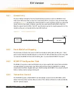
The LASI signals from each BCM84754 port are individually connected to the RTM FPGA to 
allow them to be monitored by software. The LASI signals can also generate an interrupt to the 
front blade. Refer to 

Chapter 4, 

GPS Connectors, on page 50

 for further details.

4.5.6

Fabric SFP+ Connection

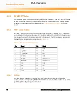
This is the same as the base SFP+ connection.  Refer to 

Chapter 4, 

SFP+ Connection, on page 42

.

4.5.6.1

SFP+ I2C Bus

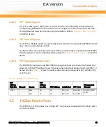
The SFP+ I2C bus signals (I2C_SDA and I2C_SCL) from each SFP+ site are individually connected 
to the BCM84754 which includes a mechanism to allow access to the port through the PHY 
management channel.

4.5.6.2

SFP+ Status Signals

The SFP+ status signals, MOD_ABS, TX_FAULT and LOS, are individually connected to the 
BCM84754 which monitors them. The signals are also connected to the RTM FPGA to allow fast 
detection of a loss of signal condition. Refer to 

Chapter 4, 

GPS Connectors, on page 50

 for further 

details.

4.5.6.3

SFP+ Control Signals

The SFP+ TX_DISABLE signal is individually connected to the BCM84754 which drives it under 
software control.

The RS0 and RS1 rate select signals from each SFP+ that are tied together and connected to the 
RTM FPGA that allows them to be controlled by software. Refer to 

Chapter 4, 

GPS Connectors, 

on page 50

 for further detail.

EA Version

Содержание RTM-ATCA-F140

Страница 1: ...Embedded Computing for Business Critical ContinuityTM RTM ATCA F140 Installation and Use P N 6806800M97A October 2011 EA Version ...

Страница 2: ...ent and to make changes from time to time in the content hereof without obligation of Emerson to notify any person of such revision or changes Electronic versions of this material may be read online downloaded for personal use or referenced in another document as a URL to a Emerson website The text itself may not be published commercially in print or electronic form edited translated or otherwise ...

Страница 3: ...nts 22 2 3 1 Environmental Requirements 22 2 4 RTM Installation and Removal 24 2 4 1 Installing the RTM 25 2 4 2 Removing the RTM 28 3 Controls LEDs and Connectors 31 3 1 Overview 31 3 2 Face Plate Connectors and LEDs 31 3 2 1 LEDs 33 4 Functional Description 35 4 1 Block Diagram 35 4 2 Management Resources 36 4 2 1 FRU Serial EEPROM 36 4 2 2 Temperature Sensors 36 4 2 3 LEDs 37 4 2 4 I2C Address ...

Страница 4: ...Fabric Ports 43 4 5 1 Fabric Connectivity 44 4 5 2 Fabric Front Blade Port Mapping 44 4 5 3 BCM84754 Configuration Flash 44 4 5 4 Transmitter Control 44 4 5 5 BCM84754 Status 45 4 5 6 Fabric SFP Connection 45 4 5 6 1 SFP I2C Bus 45 4 5 6 2 SFP Status Signals 45 4 5 6 3 SFP Control Signals 45 4 5 7 PHY Management Interfaces 46 4 6 40Gbps Fabric Ports 46 4 6 1 Fabric Connectivity 46 4 6 2 Fabric Fro...

Страница 5: ...s 53 4 8 4 BCM84754 Control and Status 53 4 8 5 BCM84740 Control and Status 54 4 8 6 Reset Handling 54 4 8 7 Synchronous Ethernet Clock Recovery 54 4 8 8 SPI Flash 55 4 8 9 FPGA Register Map 55 4 8 10 FPGA Configuration 56 4 9 Reset Scheme 56 4 10 Zone 3 Isolation 56 4 11 Power Management 57 4 11 1 Power Requirements 57 A Related Documentation 59 A 1 Emerson Network Power Embedded Computing Docume...

Страница 6: ...RTM ATCA F140 Installation and Use 6806800M97A Contents 6 Contents Contents EA Version ...

Страница 7: ...ress Map 38 Table 4 4 Front Blade Port Mapping 39 Table 4 5 SFP Connector Pin Assignment 39 Table 4 6 SFP Connector Pin Assignment 42 Table 4 7 BCM8727 PHY Addressing 43 Table 4 8 BCM84754 PHY Addressing 46 Table 4 9 QSFP Connector Pin Assignment 48 Table 4 10 BCM84740 PHY Addressing 49 Table 4 11 1PPS Input Specifications 50 Table 4 12 10MHz Input Specifications 51 Table 4 13 Time Of Day RJ45 Pin...

Страница 8: ...RTM ATCA F140 Installation and Use 6806800M97A 8 List of Tables EA Version ...

Страница 9: ...nformity TBD 18 Figure 3 1 Face Plate 32 Figure 4 1 Block Diagram 35 Figure 4 2 1GB Base Channel Interconnect 38 Figure 4 3 Fabric 10 GB Interconnect 41 Figure 4 4 Fabric 10Gb Interconnect 44 Figure 4 5 Fabric 40Gb Interconnect 47 Figure 4 6 Synchronous Ethernet Reference Recovery 55 EA Version ...

Страница 10: ...RTM ATCA F140 Installation and Use 6806800M97A 10 List of Figures EA Version ...

Страница 11: ...RTM Related Documentation lists further Emerson user manuals that are related to the RTM and the ATCA F140 Safety Notes summarizes the safety instructions in the manual Sicherheitshinweise is a German translation of the Safety Notes chapter Abbreviations This document uses the following abbreviations Abbreviation Definition AMC Alarm Management Controller ARP Address Resolution Protocol ATCA Advan...

Страница 12: ...screenoutputandcoderelatedelements or commands in body text Courier Bold Used to characterize user input and to separate it from system output Reference Used for references and for table and figure descriptions File Exit Notation for selecting a submenu text Notation for variables and keys text Notation for software buttons to click on the screen and parameter description Repeated item for example...

Страница 13: ... situation which if not avoided could result in death or serious injury Indicates a hazardous situation which if not avoided may result in minor or moderate injury Indicates a property damage message No danger encountered Pay attention to important information Notation Description Part Number Publication Date Description 6806800M97A August 2011 First edition EA Version ...

Страница 14: ...RTM ATCA F140 Installation and Use 6806800M97A About this Manual 14 About this Manual EA Version ...

Страница 15: ...l Ethernet interfaces connected to the front board through the Zone 3 connector The main features of the RTM ATCA F140 are Single slot RTM form factor 70mm x 322mm 1x 40Gbit Ethernet uplink FIX according to IEEE 802 3ba with 1 QSFP type connector 4x 10Gbit Ethernet uplinks FIX according to IEEE 802 3ap with 4 SFP type connectors 2x 10Gbit Ethernet uplinks BIX according to IEEE 802 3ap with 2 SFP t...

Страница 16: ...aracteristics Limits and Methods of Measurements EN 60950 1 This product complies with EN 60950 1 Safety of Information Technology Equipment EN55022 Class A EU The product complies with EN55022 Class A EU Information Technology Equipment Radio Disturbance Characteristics Limits and Methods of Measurements ETSI Acoustic Noise ETS 300 753 Class 3 1 The product will not prevent the system from comply...

Страница 17: ...ies with IEC 60950 1 CB Scheme including all National Deviations Safety of Information Technology Equipment Testing shall be by an accredited lab NEBS Level 3 Module is designed to pass all testing to Criteria Level 3 per Telcordia SR 3580 Safety Mark for U S and Canada The product is designed to certify to UL CSA No 60950 1 with no deviations and shall bear the Recognition Mark of an NRTL for US ...

Страница 18: ...Introduction RTM ATCA F140 Installation and Use 6806800M97A 18 Figure 1 1 Declaration of Conformity TBD EA Version ...

Страница 19: ...this manual Consult your local Emerson sales representative for the availability of further variants Table 1 2 RTM ATCA F140 Mechanical Data Data Value Dimensions 8Ux6HPformfactor 30mmx351mmx143mm includingfaceplate handles and alignment posts Weight 0 725 Kg Table 1 3 Blade Variants Ordering Information Part Number Description RTM ATCA F140 RTM for the ATCA F140 with SFP and SFP sockets EA Versio...

Страница 20: ...Introduction RTM ATCA F140 Installation and Use 6806800M97A 20 EA Version ...

Страница 21: ...cedTCA Book 1 1 This includes the following 2 0 cfm at 25 C ambient temperature 2 8 cfm at 40 C ambient temperature 4 4 cfm at 55 C ambient temperature Shipment Inspection To inspect the shipment perform the following steps 1 Verify that you have received all items of your shipment Printed Quick Start Guide and Safety Notes Summary RTM ATCA F140 Damage of Circuits Electrostatic discharge and incor...

Страница 22: ...mental Requirements The environmental conditions must be tested and proven in the shelf configuration used The conditions refer to the surrounding of the blade within the user environment The RTM is thoroughly inspected before shipment If damage has occurred or items missing during transportation contact our customer s service immediately Remove the desiccant bag shipped together with the blade an...

Страница 23: ... that forced air cooling is available in the shelf Table 2 1 Environmental Conditions Requirement Operating Non Operating Temperature and airflow per CP TA B 4 The RTM shall require no more than 2 2 CFM at the inlet ambient of 25 C 77 F Under abnormal Short Term operatingconditionssuchasan air mover failure an RTM shall require no more than 3 0 CFM at the inlet ambient of 40 C 104 F The RTM shall ...

Страница 24: ... airflowat sea level Temperature 25 C when cooled by an even airflow of 2 2 CFM 40 C to 85 C 0 C to 40 C when cooled by an even airflow of 3 0 CFM 5 C to 55 C when cooled by an even airflow of 5 0 CFM Temperature change 0 5 C min 1 C min Relative humidity 5 to 95 non condensing at 40 C 5 to 95 non condensing at 40 C Altitude 300m to 1 800m at 40 C 300m to 13 000m 1 800m to 4 000m at 30 C Between 1...

Страница 25: ...p the respective step In this case it is a purely mechanical installation Damage of Circuits Electrostatic discharge and incorrect RTM installation and removal can damage circuits or shorten its life Before touching the RTM or electronic components make sure that you are working in an ESD safe environment Damage of the RTM Incorrect installation of the RTM can cause damage of the RTM Onlyusehandle...

Страница 26: ... plate screws that secure the blade to the shelf are tight Deactivate the front blade Unlatch the lower handle by squeezing the lever and the latchtogether and turning thehandle outwardonlyenough tounlatchthe handlefrom the face plate Do not rotate the handle fully outward When the blue LED on the front blade is permanently illuminated proceed to the next step 3 Ensure that the top and bottom ejec...

Страница 27: ...atch together and hook the lower and the upper handle into the shelf rail recesses 7 Fully insert the blade and lock it to the shelf by squeezing the lever and the latch together and turning the handles towards the face plate 8 Tighten the face plate screws which secure the RTM to the shelf 9 If the front blade has already been installed as in step 2 activate the front blade by squeezing its lower...

Страница 28: ...val of the RTM It assumes that your system is powered If your system is unpowered you can disregard the blue LED and thus skip the respective step In this case it is a purely mechanical procedure 1 On the front blade unlatch the lower handle by squeezing the lever and the latch together and turning the handle outward only enough to unlatch the handle from the face plate Do not rotate the handle fu...

Страница 29: ...3 Remove face plate cables if applicable 4 Unfasten the screws of the RTM face plate until the RTM is detached from the shelf 5 Unlatch the RTM upper and lower handles and rotate fully outward 6 Remove the blade from the shelf If the LED continues to blink a possible reason may be that upper layer software rejects the blade extraction request EA Version ...

Страница 30: ...Hardware Preparation and Installation RTM ATCA F140 Installation and Use 6806800M97A 30 EA Version ...

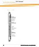
Страница 31: ...806800M97A 31 Controls LEDs and Connectors 3 1 Overview This chapter describes Face plate connectors Face plate LEDs Reset key Rear panel connectors 3 2 Face Plate Connectors and LEDs The following figure shows the face plate of the RTM EA Version ...

Страница 32: ...Controls LEDs and Connectors RTM ATCA F140 Installation and Use 6806800M97A 32 Figure 3 1 Face Plate EA Version ...

Страница 33: ... Installation and Use 6806800M97A 33 3 2 1 LEDs RTM ATCA F140providesfourpanel visibleLEDsthatprovidethestandardATCAmanagement LED functions Red out of service Green in service Blue hot swap initializing shutting down Amber attention EA Version ...

Страница 34: ...Controls LEDs and Connectors RTM ATCA F140 Installation and Use 6806800M97A 34 EA Version ...

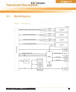
Страница 35: ...Chapter 4 RTM ATCA F140 Installation and Use 6806800M97A 35 Functional Description 4 1 Block Diagram Figure 4 1 Block Diagram EA Version ...

Страница 36: ...agement power and thus is available regardless of payload power This serial EEPROM is intended to hold FRU data and any additional parameters that are required 4 2 2 Temperature Sensors The RTM ATCA F140 has provision for three temperature sensors that are located on the primary side of the board close to the top middle and bottom of the RTM These sensors are I2C based LM75 type devices The over t...

Страница 37: ...I O expander pins and the anodes are connected to the management 3 3V supply through current limiting resistors selected to limit the LED current to 15mA Since the I Os power up in the high state this ensures that the LEDs will remain off until explicitly turned on by the IPMC For the blue LED an external FET inverter is used to ensure the LED is on at power up and a charge pump is used to provide...

Страница 38: ...e routed directly from the zone 3 connectors to four SFP sites as shown in Figure 4 2 These are all dedicated ports on the front blade base switch The RTM ATCA F140 does not include AC coupling capacitors on the inputs from the front blade since they are provided by the SFP module Table 4 3 I2C Bus Address Map Address Device 0x40 I OExpander LED control 0x90 Temperature sensor top 0x92 Temperature...

Страница 39: ...ngeopticalconnection RefertotheATCA F140 Installation andUse Manual for a list of SFP devices tested with this product The following table shows the SFP connector pin assignments Table 4 4 Front Blade Port Mapping RTM Port Front Blade Base Switch Port ETH1 ge20 ETH2 ge21 ETH3 ge22 ETH4 ge23 Table 4 5 SFP Connector Pin Assignment Pin Signal Pin Signal 1 GND 11 GND 2 TX_FAULT 12 RX 3 TX_DISABLE 13 R...

Страница 40: ...52 for details 4 3 3 2 SFP Status Signals The SFP status signals MOD_ABS TX_FAULT and LOS are individually connected to the RTM FPGA to allow monitoring by the service processor Refer to the Chapter 4 FPGA on page 52 for details 4 3 3 3 SFP Control Signals The SFP control signals TX_DISABLE and RATE_SEL are individually connected to the RTM FPGA to allow control by the service processor Refer to t...

Страница 41: ...1 These ports connect directly to dedicated ports on the ATCA F140 front blade base switch BIX_XG0 is connected to BCM8727 channel 2 while BIX_XG1 is connected to BCM8727 channel 1 4 4 3 BCM8727 Configuration Flash TheBCM8727requiresanexternalSPIFlashtostoremicrocodefortheinternalmicrocontroller A single SPI Flash is connected to the FPGA and the SPI bus from the BCM8727 is similarly connected to ...

Страница 42: ...1 GB optical or copper SFP modules Refer to the ATCA F140 Installation and Use Manual for a list of SFP devices tested with this product The SFP connector assignment for the 10 Gbps serial interface is described in Table 4 6 4 4 6 1 I2C Bus The SFP I2C bus signals I2C_SDA and I2C_SCL from each SFP site are individually connected to the corresponding BCM8727 which includes a mechanism to allow acce...

Страница 43: ...ted totheRTMFPGA that allows them to be controlled by software Refer to Chapter 4 FPGA on page 52 for further details 4 4 6 4 PHY Management Interfaces The BCM8727 provides a single MDC MDIO management port to access both channels and allows bit 0 of the PHY address for each channel to be individually programmed with bits 1 4 being common Table 4 7 shows the address allocation and management port ...

Страница 44: ...ort Mapping Each fabric switch porton the front blade consists offourSERDESpairs The fourfabric channel XFI ports connect to front blade port FIX_P15 This is a dedicated port on the ATCA F140 front blade fabric switch 4 5 3 BCM84754 Configuration Flash The BCM84754 requires an external SPI Flash to store microcode for the internal microcontroller A single SPI Flash is connected to the FPGA and the...

Страница 45: ...ted to the BCM84754 which includes a mechanism to allow access to the port through the PHY management channel 4 5 6 2 SFP Status Signals The SFP status signals MOD_ABS TX_FAULT and LOS are individually connected to the BCM84754 which monitors them The signals are also connected to the RTM FPGA toallow fast detectionof aloss of signal condition Refer to Chapter 4 GPS Connectors on page 50for furthe...

Страница 46: ... a BCM84740 quad XLAUI to SFI PHY which then connects to a single QSFP connector using an SFI interface as shown in Figure 4 5Fabric 40Gb Interconnect When the fabric switch is configured for XLAUI mode the QSFP slotsupportsasingle40GbElogicalconnection Whenthefabricswitchisconfiguredfor4xXFI mode the QSFP slot supports four 10GbE connections This mode assumes the use of a fiber breakout cable on ...

Страница 47: ...l microcontroller A single SPI Flash is connected to the FPGA and the SPI bus from the BCM84740 is similarly connected to the FPGA Register settings in the FPGA allow the BCM84740 to connect to the SPI Flash as well as provide a programming port 4 6 4 Transmitter Control QSFP does not define a hardware signal for transmitter control Software controls the transmitter via byte 86 in the QSFP memory ...

Страница 48: ...r and optical direct attach cables The site is designed to support power level 2 modules which are rated up to 2W Refer to the ATCA F140 Installation and Use Manual for a list of QSFP devices tested with this product The QSFP connector assignment for the 40Gbps serial interface is described in Table 4 9 QSFP Connector Pin Assignment Table 4 9 QSFP Connector Pin Assignment Pin Signal Pin Signal 1 G...

Страница 49: ...ODE signal is connected to the BCM84740 This allows software control of the power mode or hardware control through deassertion of the TXONOFF signal 4 6 7 PHY Management Interfaces The BCM84740 provides a single MDC MDIO management port to access all four channels and allows bits 0 and 1 of the PHY address for each channel to be individually programmed with bits 2 4 being common Table 4 10 BCM8474...

Страница 50: ...CA F140forreceptionofa 1PPS signal from a GPS receiver Below are the characteristics of this input 1 Fabric b01 1 FIX_P14 Lane 1 2 Fabric b10 2 FIX_P14 Lane 2 3 Fabric b11 3 FIX_P14 Lane 3 Table 4 10 BCM84740 PHY Addressing continued PHY Address High Bits Channel Source PHY Address Low Bits PHY Address Switch Port QSFP Port Management Channel Table 4 11 1PPS Input Specifications 1PPS SMA Input Wav...

Страница 51: ...serial RS 485 RS 422 time of day information from a GPS receiver The serial format is 9600 baud 8data bits no parity and 1 stop bit There is also a 1PPS input channel on the RJ45 connector for GPS receivers that transmit 1PPS serially Below is the pinout of this port Table 4 12 10MHz Input Specifications 10MHz SMA Input Waveform Sine wave Minimum Amplitude 0 5Vp p Maximum Amplitude 5 0Vp p Impedan...

Страница 52: ...programmer and multiplexing for BCM8727 BCM84754 and BCM84740 configuration UART with selectable outputs for the optional GPS receiver functionality not initially implemented 4 8 1 Front blade Interface The RTM ATCA F140 includes an SPI interface between the front blade service processor and the RTM FPGA There is also an active low interrupt line to the front blade to request service 4 8 2 SFP SFP...

Страница 53: ...tting the phys into a low power mode The RTM FGPA provides access to the following BCM8727 status signals PCMULK PCDRLK PLOSB LASI Each signal can be programmed to cause an interrupt when its state changes 4 8 4 BCM84754 Control and Status The RTM FPGA provides register access to the BCM84754 TXONOFF signals This allows the PHYs to be placed into low power mode and disables the associated SFP tran...

Страница 54: ...FP port This allows the front blade control processor to reset the PHYs and QSFP At system reset as indicated by the zone 3 RTM_RST signal the PHYs and QSFP are forced into reset until this is cleared by a register write This is to ensure that the PHYs are in reset until the telecom clock subsystem has been programmed if necessary to provide the PHY reference clocks 4 8 7 Synchronous Ethernet Cloc...

Страница 55: ...ct to the FPGA along with three SPI Flash devices one for each type Register settings allow access to be granted to any of the PHYs and also provide a programming port 4 8 9 FPGA Register Map Details of the FPGA register map are included in the RTM FPGA section of the ATCA F140 FPGA design guide Figure 4 6 Synchronous Ethernet Reference Recovery Digital Frequency Synthesizer x32 Synchronous Divide...

Страница 56: ...ly resets the RTM FPGA The BCM8727 BCM84754 BCM84740 and QSFP slot are reset from a secondary reset generated by the RTM FPGA This allows software control ofthe PHYand QSFP resets in additionto hardware control via the RTM_RST signal Afterthe hardware reset the PHYs and QSFP are held in reset until released by software 4 10 Zone 3 Isolation Since the front blade does not apply payload power to the...

Страница 57: ...separate power supplies using the Zone 3 connectors 3 3 V management power one pin 12 V payload power four pins Themaximum currentdraw whichislimited by thepin scurrenthandlingcapability is0 8Afor the management power and 3 2A for the payload power The management power is used to directly power the devices connected to the front blade I2C bus namely for serial EEPROM temperature sensors and I O ex...

Страница 58: ...Functional Description RTM ATCA F140 Installation and Use 6806800M97A 58 EA Version ...

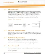
Страница 59: ...ing publications by contacting your local Emerson Sales Office For released products you can also visit our Web site for the latest copies of our product documentation 1 Go to http www emersonnetworkpower com EmbeddedComputing 2 Under Resources click Technical Documentation 3 Enter the publication number or the complete name of the product in the search Table A 1 Related Documentation Document Tit...

Страница 60: ...Related Documentation RTM ATCA F140 Installation and Use 6806800M97A 60 EA Version ...

Страница 61: ... representative The product has been designed to meet the standard industrial safety requirements It must not be used except in its specific area of office telecommunication industry and industrial control Only personnel trained by Emerson or persons qualified in electronics or electrical engineering are authorized to install remove or maintain the product The information given in this manual is m...

Страница 62: ...ent Board products are tested in a representative system to show compliance with the above mentioned requirements A proper installation in a compliant system will maintain the required performance Use only shielded cables when connecting peripherals to assure that appropriate radio frequency emissions compliance is maintained Installation Damage of the RTM and Additional Devices and Modules Incorr...

Страница 63: ... or blades Operation Damage of the RTM High humidity and condensation on the RTM surface causes short circuits Do not operate the RTM outside the specified environmental limits Make sure the RTM is completely dry and there is no moisture on any surface before applying power Cabling and Connectors Environment Always dispose of used blades system components and RTMs according to your country s legis...

Страница 64: ...les which are classified as laser products make sure to comply to the respective regulations Eye Damage Optical SFP SFP modules may emit laser radiation when no cable is connected This laser radiation is harmful to your eyes Do not look into the optical lens at any time SFP SFP Module Damage The optical port plug protects the optical fibres against dirt and damage Dirt and damage can render the SF...

Страница 65: ...ten wenden Sie sich bitte an die für Sie zuständige Geschäftsstelle von Emerson Das System erfüllt die für die Industrie geforderten Sicherheitsvorschriften und darf ausschließlich für Anwendungen in der Telekommunikationsindustrie und im Zusammenhang mit Industriesteuerungen verwendet werden Einbau Wartung und Betrieb dürfen nur von durch Emerson ausgebildetem oder im Bereich Elektronik oder Elek...

Страница 66: ...rungen verursachen In diesem Fall kann vom Betreiber verlangt werden angemessene Maßnahmen durchzuführen Installation Beschädigung des RTMs und von Zusatzmodulen Fehlerhafte Installation von Zusatzmodulen kann zur Beschädigung des RTMs und der Zusatzmodule führen Lesen Sie daher vor der Installation von Zusatzmodulen die zugehörige Dokumentation Beschädigung von Schaltkreisen Elektrostatische Entl...

Страница 67: ...rte Garantie für Blades und Backplanes erlöschen lassen Betrieb Beschädigung des Blades Die RJ 45 Stecker an der Frontblende sind für Anschlüsse vom Typ Twisted Pair Ethernet TPE oder E1 T1 J1 vorgesehen Der Anschluss eines E1 T1 J1 Interfaces an einen Ethernet Stecker kann zur Zerstörung des Blades führen Stellen Sie daher sicher dass TPE Stecker an Ihrem Arbeitsplatz eindeutig als Netzwerkstecke...

Страница 68: ...nn Sie solche SFP SFP Module installieren und betreiben so gelten die entsprechenden Bestimmungen für Laserprodukte für das gesamte RTM Werden diese Bestimmungen nicht eingehalten so können Verletzungen die Folge sein Wenn Sie SFP SFP Module betreiben die als Laserprodukte klassifiziert sind stellen Sie sicher dass die entsprechenden Bestimmungen für Laserprodukte eingehalten werden Verletzungsgef...

Страница 69: ...bbreviations 11 B block diagram 35 C connectors 31 controls 31 conventions 12 E environmental requirements 22 F face plate 31 features 15 functional description 35 I installation hardware 21 installation RTM 25 L leds 31 R removal RTM 28 Index EA Version ...

Страница 70: ...Index RTM ATCA F140 Installation and Use 6806800M97A 70 EA Version ...

Страница 71: ...EA Version ...

Страница 72: ...rk Power logo are trademarks and service marks of Emerson Electric Co All other product or service names are the property of their respective owners 2009 Emerson Electric Co Emerson Network Power The global leader in enabling Business Critical Continuity AC Power Systems Connectivity DC Power Systems Embedded Computing Embedded Power Integrated Cabinet Solutions Outside Plant Power Switching Contr...

Отзывы: