13
13
emersonfans.com
Please contact 1-800-654-3545 for further assistance
U.L. Model No.: CF905-1
7. Wall Control Installation
(Continued)
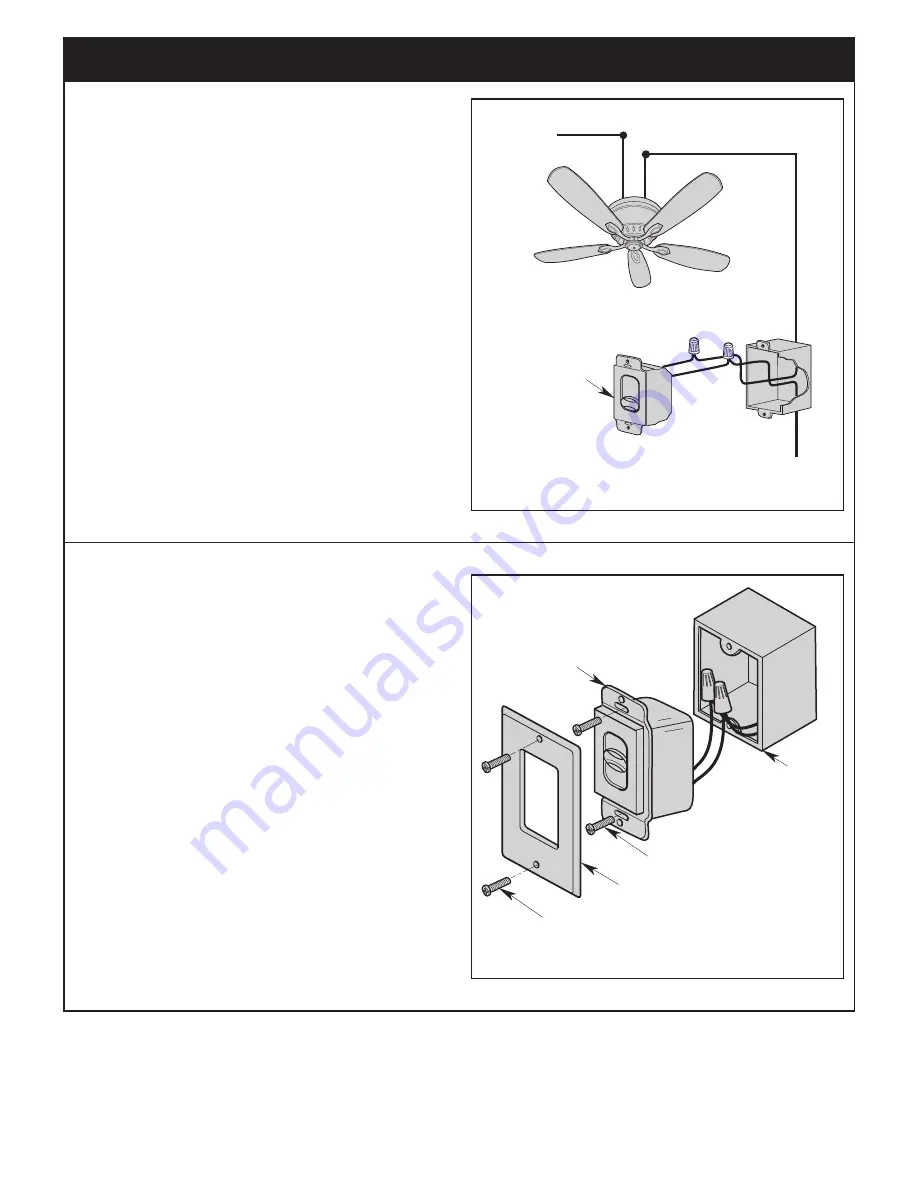
7.3
Slide the 4-Speed Slide Wall Control in the OFF position
(0).
Connect One BLACK Wire from the 4-Speed Slide Wall
Control to the Fan/Motor Wire with a Wire Connector
(supplied) (Figure 20).
Connect the Other BLACK Wire from the 4-Speed
Slide Wall Control to the 120VAC Hot Wire with a Wire
Connector (supplied).
NOTE: Use wire connectors (supplied) to secure
electrical connections.
MOTOR LOAD
1.2 AMP MAXIMUM
TO 120VAC
SOURCE HOT
BLACK
BLACK
4
0
3
2
1
TO
NEUTRAL
TO FAN MOTOR LOAD
4-SPEED SLIDE
WALL CONTROL
OFF (0) POSITION
Figure 20
7.4
Attach the 4-Speed Slide Wall Control to the Wall Outlet
Box with Two 6-32 x 3/4” Screws (supplied).
Position the Faceplate (supplied) onto the 4-Speed
Slide Wall Control. Using the Two 6-32 x 1/4” Screws,
Screw the Faceplate and 4-Speed Slide Wall Control to
the Wall Outlet Box (Figure 21).
Restore Power at the Main Fuse Box or Circuit Breaker
Panel.
4-SPEED SLIDE
WALL CONTROL
4
0
3
2
1
6-32 x 3/4" SCREWS (2)
6-32 x 1/4" SCREWS (2)
FACEPLATE
OUTLET
BOX
Figure 21


