Emerson PRIMA SNUGGER CF905BS01 Скачать руководство пользователя страница 2

2


 U.L. Model No.: CF905-1

Table of Contents

Safety Instructions

TO REDUCE THE RISK OF FIRE, ELECTRICAL 

SHOCK, OR INJURY TO PERSONS, OBSERVE THE 

FOLLOWING:

a. Use this unit only in a manner intended by the 

manufacturer.  If you have questions, contact the 

manufacturer.

b. Before servicing or cleaning unit, switch power 

off at service panel and lock service panel 

disconnecting means to prevent power from 

being switched on accidentally. When the service 

disconnecting means cannot be locked, securely 

fasten a warning device, such as a tag, to the 

service panel.


WARNING

!

To reduce the risk of electrical shock, this fan must be 

installed with an isolating wall control/switch.

To reduce the risk of fire or electrical shock, this fan 

should only be used with fan speed control, Model No. 

SW46 / U.L. Model No. UC9020, manufactured by Rhine 

Electric Co., Ltd.

To avoid fire, shock or injury, do not use an Emerson 

or any other brand of control not specifically approved 

for this fan.

This product is designed to use only those parts 

supplied with this product and/or any accessories 

designated specifically for use this product. 

Substitution of parts or accessories not designated 

for use with this product by Emerson could result in 

personal injury or property damage.

To reduce the risk of personal injury, do not bend 

the blade flange when installing the blade flanges, 

balancing the blades or cleaning the fan. Do not insert 

foreign objects in between rotating fan blades.


WARNING

!

Additional Safety Instructions for Installation

1. To avoid possible shock, be sure electricity is turned 

off at the fuse box before wiring, and do not operate 

fan without blades.

2. All wiring must be in accordance with the National 

Electrical Code “ANSI/NFPA 70-2017” and Local 

Electrical Codes. Use the National Electrical Code 

if Local Codes do not exist. The ceiling fan must be 

grounded as a precaution against possible electrical 

shock. Electrical installation should be made or 

approved by a licensed electrician.

3.  The outlet box and joist must be securely mounted 

and capable of reliably supporting at least 50 pounds. 

Use only U.L. outlet boxes listed as “Acceptable for 

Fan Support of 22.7kg. (50 lbs.) or less”, and use the 

mounting screws provided with the outlet box. Most 

outlet boxes commonly used for support of light fixtures 

are not acceptable for fan support and may need to be 

replaced. Consult a qualified electrician if in doubt.

4. The downrod furnished with the fan provides the 

minimum recommended floor to fan blade clearance 

for an 8 foot ceiling.

5. Follow the recommended instructions for the proper 

method of wiring your ceiling fan. If you do not know 

enough about electrical wiring, have your fan installed 

by a licensed electrician.

NOTE:


This fan is suitable for use with solid-state speed 

controls.

1. Read your owner’s manual carefully and keep it for 

future reference.

2. Be careful of the fan and blades when cleaning, 

painting, or working near the fan. Always turn off the 

power to the ceiling fan before servicing.

3.  Do not put anything into the fan blades while they are 

turning.

4. Do not operate reverse switch until fan blades have 

come to a complete stop.

READ AND SAVE THESE INSTRUCTIONS

Section Page
Safety Instructions   . . . . . . . . . . . . . . . . . . . . . . . . . . . 2
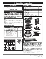
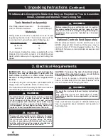
1. Unpacking Instructions   . . . . . . . . . . . . . . . . . . . . .3-4
2. Electrical Requirements  . . . . . . . . . . . . . . . . . . . . .  4
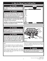
3. How to Hang Your Ceiling Fan  . . . . . . . . . . . . . . . . 5
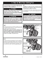
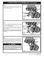
4. How to Wire Your Ceiling Fan    . . . . . . . . . . . . . . .6-7
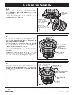
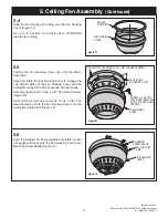
5. Ceiling Fan Assembly  . . . . . . . . . . . . . . . . . . . . .8-11
6. Operating Your Ceiling Fan . . . . . . . . . . . . . . . . . . 11

Section Page
7. Wall Control Installation . . . . . . . . . . . . . . . . . . . 12-13
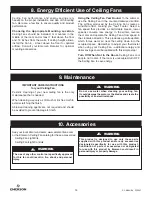
8. Energy Efficient Use of Ceiling Fans . . . . . . . . . . . 14
9. Maintenance  . . . . . . . . . . . . . . . . . . . . . . . . . . . . . 14
10. Accessories    . . . . . . . . . . . . . . . . . . . . . . . . . . . . 14
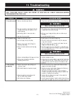
11. Troubleshooting   . . . . . . . . . . . . . . . . . . . . . . . . . 15
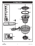
12. Repair Parts   . . . . . . . . . . . . . . . . . . . . . . . . . . 16-17
Ceiling Fan Limited Warranty   . . . . . . . . . . . . . . . . . . 19

To reduce the risk of injury, install the fan so that the 

blades are at least 7 ft. (2.1m) above the floor.


CAUTION

!

Содержание PRIMA SNUGGER CF905BS01

Страница 1: ...ng Fan Owner s Manual Model Numbers Net Weight 18 3 Lbs www emersonfans com Questions problems missing parts Before returning to the store call Customer Service 8 a m 6 p m Eastern Monday Friday 1 800 654 3545 TRADITIONAL CF905BS01 Brushed Steel CF905ORB01 Oil Rubbed Bronze CF905SW01 Satin White CF905VNB01 Venetian Bronze 4 0 3 2 1 ...

Страница 2: ...Use the National Electrical Code if Local Codes do not exist The ceiling fan must be grounded as a precaution against possible electrical shock Electrical installation should be made or approved by a licensed electrician 3 The outlet box and joist must be securely mounted and capable of reliably supporting at least 50 pounds Use only U L outlet boxes listed as Acceptable for Fan Support of 22 7kg ...

Страница 3: ...If any parts are missing contact your local retailer or catalog outlet for replacement before proceeding 1 2 Remove the Fan Assembly from the protective plastic bag Place the Fan Assembly into the upper foam pad with the Wires facing up The upper foam pad serves as a holder for the Fan during the first stages of assembly 4 0 3 2 1 H G F E D C B A A B C D F G E H 4 0 3 2 1 PACKAGE CONTENTS 7 3 4 2 ...

Страница 4: ...st outlet boxes commonly used for support of light fixtures are not acceptable for fan support and may need to be replaced Consult a qualified electrician if in doubt WARNING Turning off wall switch is not sufficient To avoid possible electrical shock be sure electricity is turned off at the main fuse box before wiring All wiring must be in accordance with National and Local codes and the ceiling ...

Страница 5: ...outlet box Most outlet boxes commonly used for support of light fixtures are not acceptable for fan support and may need to be replaced Consult a qualified electrician if in doubt WARNING 3 1 Disconnect Electrical Power to the Branch Circuit at the Circuit Breaker or Fuse Box before attempting to install the Ceiling Fan Hanger Bracket on the Outlet Box Pull the Electrical Supply Black White and Gr...

Страница 6: ...use box before wiring NOTE If you are not sure if the outlet box is grounded contact a licensed electrician for advice as it must be grounded for safe operation WARNING This product is designed to use only those parts supplied with this product and or any accessories designated specifically for use with this product Substitution of parts or accessories not designated for use with this product by E...

Страница 7: ...nnector supplied Figure 6 Cap the Fan Motor Assembly Blue Wire with a 12 ga Wire Connector supplied if using the supplied Wall Control Figure 6 NOTE If you are using an Emerson Light Fixture with your fan see the Light Fixture Owner s Manual for wiring Figure 6 FAN MOTOR ASSEMBLY OUTLET BOX 4 6 After connections have been made turn Wires upward and carefully push the Wires into the Outlet Box with...

Страница 8: ...ards and mate it up against the Ceiling Mounting Plate Align and rotate the Fan Motor Assembly to engage the Two Keyhole Slots with the Ceiling Mounting Plates Two Loosened Screw Heads Figure 9 Securely tighten both 10 24 x 3 8 Pan Head Screws Figure 9 Reinstall the previously removed 10 24 x 3 8 Pan Head Screw with Lockwasher to secure the Fan Motor Assembly onto the Ceiling Mounting Plate Figure...

Страница 9: ...AD SCREWS 5 5 Position the Fan Housing Cover over the Fan Motor Assembly Align and rotate the Fan Housing Cover to engage the Two Slotted Holes of the Fan Housing Cover with the Ceiling Mounting Plate Two Loosened Screws Heads Securely tighten both 10 24 x 3 8 Pan Head Screws Figure 12 Reinstall the previously removed 10 24 x 3 8 Pan Head Screw to secure the Fan Housing Cover onto the Ceiling Moun...

Страница 10: ... not to scratch the fan housing when installing the blade assemblies SWITCH HOUSING CONNECTOR REMOVE SWITCH HOUSING MOUNTING SCREWS 4 MOTOR CONNECTOR 5 9 Engage the Switch Housing Assembly Connector with the Fan Motor Assembly Connector Figure 16 NOTE The two connectors are keyed and color coded and must be mated correctly color to color before they can be engaged Make sure the Connector Latch clo...

Страница 11: ...supply wire Position the Switch Housing Assembly on the Switch Housing Plate Align the Switch Housing Assembly Holes with the Switch Housing Plate Holes Secure the Switch Housing Assembly by reinstalling the Four Switch Housing Plate Screws removed previously Figure 17 Figure 17 6 Operating Your Ceiling Fan REVERSE SWITCH Figure 18 6 1 Restore Electrical Power to the Outlet Box by turning the Elec...

Страница 12: ...er panel Turning off wall switch is not sufficient To avoid possible electrical shock be sure electricity is turned off at the main fuse box before wiring All wiring must be in accordance with National and Local codes and the ceiling fan must be properly grounded as a precaution against possible electrical shock WARNING To avoid fire or shock follow all wiring instructions carefully Any electrical...

Страница 13: ...onnectors supplied to secure electrical connections MOTOR LOAD 1 2 AMP MAXIMUM TO 120VAC SOURCE HOT BLACK BLACK 4 0 3 2 1 TO NEUTRAL TO FAN MOTOR LOAD 4 SPEED SLIDE WALL CONTROL OFF 0 POSITION Figure 20 7 4 Attach the 4 Speed Slide Wall Control to the Wall Outlet Box with Two 6 32 x 3 4 Screws supplied Position the Faceplate supplied onto the 4 Speed Slide Wall Control Using the Two 6 32 x 1 4 Scr...

Страница 14: ... Ceiling Fan performance and energy savings rely heavily on the proper installation and use of the ceiling fan Here are a few tips to ensure quality and product performance Choosing the Appropriate Mounting Location Ceiling Fans should be installed or mounted in the middle of the room and at least 7 feet above the floor and 18 inches from the walls If ceiling height allows install the Fan 8 9 feet...

Страница 15: ... to make sure wire connectors in switch housing rattling are not rattling against each other or against the interior wall of the switch housing 5 Screws holding blades to flanges are loose 5 Tighten screws securely 6 Motor noise caused by solid state 6 Some fan motors are sensitive to signals from Solid State variable speed control variable speed controls If Solid State Control is used and motor n...

Страница 16: ...16 U L Model No CF905 1 12 Repair Parts 2 1 12 14 3 6 7 11 10 4 9 5 PARTS BAG 9 15 10 11 12 13 14 8 4 0 3 2 1 ...

Страница 17: ...1 2 Fan Housing Trim Ring 764130 BS 764130 ORB 764130 SW 764130 VNB 3 Fan Housing Cover 764131 BS 764131 ORB 764131 SW 764131 VNB 4 Fan Blades 5 per set 765174 DC CH 765174 DC WA 765174 SW MP 765174 DC WA 5 Fan Blade Flanges 5 per set 764105 BS 764105 ORB 764105 SW 764105 VNB 6 Wiring Harness 764132 BK 764132 BK 764132 SW 764132 BK 7 Switch Housing Cover 764110 BS 764110 ORB 764110 SW 764110 VNB 8...

Страница 18: ...18 U L Model No CF905 1 Notes ...

Страница 19: ... normal wear and tear rather than due to defects in materials or workmanship Loss or damage resulting from conditions beyond our reasonable control including without limitation unforeseeable operating environmental conditions repairs not made at Our factory or authorized service center use of parts or accessories not provided to You as part of this warranty by Our factory or authorized service cen...

Страница 20: ... can be found on the carton and on top of the fan housing stamped in ink on a white label You should record this data above and keep it in a safe place for future use 1 800 654 3545 www emersonfans com Retain this manual for future use Questions problems missing parts Before returning to the store call Customer Service 8 a m 6 p m Eastern Monday Friday DIVISION OF LUMINANCE BRANDS 1945 S Tubeway A...

Отзывы: