11
emersonfans.com
Please contact 1-800-654-3545 for further assistance
U.L. Model No.: CF905-1
5. Ceiling Fan Assembly
(Continued)
SWITCH
HOUSING
ASSEMBLY
SWITCH HOUSING PLATE SCREWS (4)
5.10
NOTE: To install an accessory light kit, remove
switch housing and make light kit electrical
connections to blue and white leads marked
“For Light” in the switch housing. Follow light
kit instructions for wiring and installation. Then
reinstall switch housing as outlined in Step 5.9.
NOTE: The supplied wall control can not be used
to control the operation of an accessory light
kit. The blue fan wire located on top of the motor
assembly must be connected to a second “HOT”
supply wire that is not attached to the supplied
wall control. See your Emerson dealer for optional
remote control options that can control the fan and
accessory light kit using a single “HOT” supply
wire.
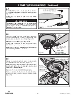
Position the Switch Housing Assembly on the Switch
Housing Plate.
Align the Switch Housing Assembly Holes with the
Switch Housing Plate Holes.
Secure the Switch Housing Assembly by reinstalling the
Four Switch Housing Plate Screws removed previously
(Figure 17).
Figure 17
6. Operating Your Ceiling Fan
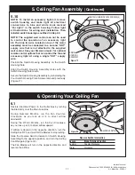
REVERSE SWITCH
Figure 18
6.1
Restore Electrical Power to the Outlet Box by turning
the Electricity on at the Main Fuse Box.
During Summer Months, run the Fan Counter-
Clockwise, as you look up at it, to direct airflow
downward.
During the Winter Months, run the Fan Clockwise,
as you look up at it, to direct airflow upward.
If airflow is desired in the opposite direction, turn the
Ceiling Fan OFF and wait for the Blades to stop turning.
Slide the Reverse Switch (located on Switch Housing
Assembly) to the opposite position, and turn the Ceiling
Fan ON again (Figure 18).
The Fan Blades will turn in the opposite direction and
reverse the airflow.
Reverse Switch Information
Season
Blade Rotation Direction
Summer Counter-Clockwise
Winter Clockwise


