


52
User Manual 10H52188UM60 - Rev. 2 - 09/2012
UPS Operation Instructions
Liebert NXC
Caution
Before performing this procedure, you should check the LED information first, and make sure the bypass is normal and inverter
synchronized. Otherwise, it may result in the load power interruption for a while.
1. Press the OFF for 2 seconds.
The inverter indicators are off and the buzzer alarms. The load transfers to the static bypass, and the inverter shuts down.
Note
Press the ALARM CLEAR button can silence the alarm, but the alarm message of the the LCD does not disappear until the alarm status is
cleared.
2. Close the maintenance bypass MCB (QS3) on the UPS rear panel, and the maintenance bypass can supply power to the load.
Warning
If you wish to maintain the UPS module, open the battery MCB QS6 and QS7, and you should wait 10 minutes for the internal DC bus
capacitance voltage discharging.
3. Disconnect the main/bypass input switch and output switch (MCB QS1, QS2 and QS4)
Caution
1. When the UPS is in Maintenance Bypass mode, the load does not have the mains abnormal protection.
2. After the UPS transfers to the maintenance bypass, the UPS is not in operation, and the LCD is not displayed, and only the user terminal
block is electrified. Be careful when removing the UPS module for maintainance.
6.2.5
Transfer From Maintenance Bypass Mode To Inverter Mode
After UPS maintenance, you can use this procedure to transfer the load from the maintenance bypass to the inverter.
Warning
As no auxiliary contact information of the maintenance bypass MCB QS3 is introduced into the UPS, UPS operation restoration after
maintenance must be done strictly following this procedure. Failure to observe this may cause damage to the equipment.
1. Close the output MCB QS4 on the rear panel of the UPS.
2. Close the mains input MCB QS1 and bypass input MCB QS2 on the rear panel of the UPS.
3. Wait until the UPS starts to operate in Bypass mode, and open the maintenance bypass MCB QS3 on the rear panel of the
UPS.
4. Press the ON button on the operation and display panel of the UPS, and the UPS transfers to Inverter mode.
6.2.6
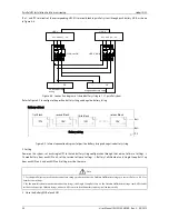
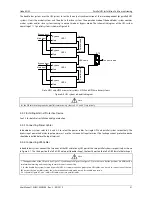
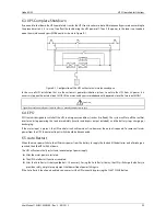
Operation with the external Maintenance Bypass in parallel systems
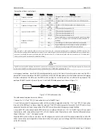
Refer also to Figure 4-1.
In parallel UPS systems, the internal maintenance bypass switches QS3 must be switched off and locked in this position.
Ensure that all the internal bypass switches (STS) are in “ON” status ( check status on displays) before switching the
maintenance bypass switch (“Qout BYP) on.
There is no interruption in the power supply to the load.
Ensure that all the internal bypass switches (STS) are in “ON” status ( check status on displays) before switching the
maintenance bypass switch (“Qout BYP) off.
There is no interruption in the power supply to the load.
To disconnect the load, switch off the “Qout of all UPS” switch, followed by the external maintenance bypass switch.


