


User Manual 10H52188UM60 - Rev. 2 - 09/2012
39
Liebert NXC
Parallel UPS Installation And Commissioning
4.4
Commissioning Parallel System
4.4.1
Check Before Power-On
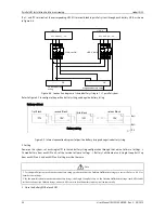
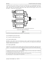
1. Check and confirm that the power distribution mode of the UPS is correct; that the connections of the power cables and
signals cable are correct and there is no short circuit.
2. Check that the battery installation and cable connection is correct and there is no short circuit, and that the positive pole
and negative pole of the battery is correct. Especially when each UPS of the parallel system shares battery string, check these
items carefully.
3. Check all the working status of the parallel system, ensure that the phase sequence of the mains, bypass and output of each
UPS is correct and consistent, that the parallel cable connection is reliable, and that the user load is not connected during
power-on.
4. Measure and confirm that the mains voltage and frequency is normal.
5. The output terminals of the UPS are energized upon the power-on. If the load is connected with the output terminals, make
sure that the power to the load is safe.
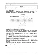
Warning
The UPS will be live upon the power-on. When the bypass of the single unit in the parallel system is not consistent, a system fault may
occur, check and confirm the bypass before power-on.
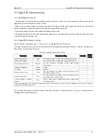
4.4.2
Parallel System Parameters Setting
The parallel parameters for all the UPS units in parallel system should be set.
Power ON the each UPS of the parallel system according to step 1) ~ step 4) in 4.4.3
,
it’s prohibited to start the inverter. Set
the parallel parameters according to Table 4-2.
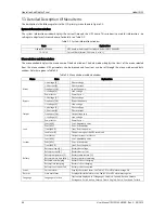
Table 4-2 Parallel parameters setting
Parameters
Default value
Parallel parameters setting
ParamSet
Display
Setting
Single Group Batt Cap
0014
Set the parameter according to the actual battery capacity
x
Battery Cells Number
32
Set the parameter according to the actual battery number
x
Equalize Charge Allowed
Enabled
Set the parameter according to the actual battery
characteristic
x
Shared Battery
Disabled
Select “Enabled” if there is shared battery, select “Disabled”
if there is no shared battery
x
System Configuration
Single
Parallel
x
Parallel requisite units
1
Set the paramerter to “3” if there are four UPS to form 3 + 1
parallel system
x
Parallel Redundant Units
0
Set the paramerter to “1” if there are four UPS to form 3 + 1
parallel system
x
ECO Mode
Normal
Normal
x
Output frencency level
50Hz
Set the parameter according to the actual power grid,
50Hz/60Hz can be selected
x
Output voltage level
400V
Set the parameter according to the actual power grid,
380V/400V/415V can be selected
x
3 Phase Output or 1 Phase
Output
Three
Select “Three” when is 3 Phase Output, select ”Single”
when is 1 Phase Output
x
Note: output frequency level and output voltage level will be active after power-off, but will not be displayed on LCD panel, the settings
will be valid after manual power-off.
The default values of other parameters are listed in Table 3-4.
For the parallel system with N + X (2
≤
N + X
≤
4), set ‘System Configuration’ to ‘Parallel’, ‘Parallel requisite units’ to ‘N’ (1
≤
N
≤
4), ‘Parallel Redundant Units’ to ‘X’ (0
≤
X
≤
3). Take the 3 + 1 parallel system for example, set ‘System Configuration’ to
‘Parallel’, ‘Parallel requisite units’ to ‘3’, ‘Parallel Redundant Units’ to ‘1’.


