


User Manual 10H52188UM60 - Rev. 2 - 09/2012
25
Liebert NXC
Single UPS Installation And Commissioning
3.4.1
Connecting I/O Cables
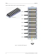
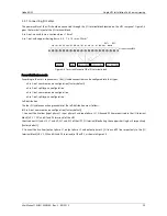
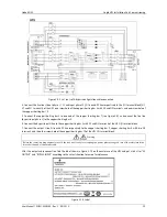
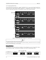
The power cables of the UPS should be connected through the I/O terminal block located on the UPS rear panel. Figure 3-4
gives the terminal layout of the I/O terminal block.
3-in 3-out: max. cable cross-sectional area = 16mm
2
3-in 1-out: with copper shorting bars n. 4, 5, 7, 8, 10 = max. 25mm
2
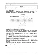
Figure 3-4 Terminals layout of the I/O terminal block
Power distribution mode
According to the user’s requirements, the I/O cable connections can be configured into four types:
3-in 3-out, common source configuration (factory default),
3-in 3-out, split-bypass configuration,
3-in 1-out, common source configuration,
3-in 1-out, split-bypass configuration.
Self-distribution
The four I/O cable connection procedures of the self-distribution are as follows:
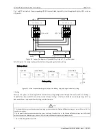
3-in 3-out, common source configuration (factory default)
1. Connect the live lines (input phase L1, input phase L2 and input phase L3), N line and PE line respectively to the I/O terminal
block (U1, V1, W1 and N1 and PE terminals) of the UPS.
Short connect U1 and U2, V1 and V2, W1 and W2 of the UPS I/O terminal block using the copper shorting bar 3 respectively
(factory default).
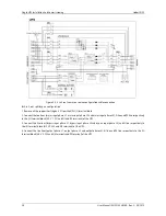
2. Connect the live lines (output phase L1, output phase L2 and output phase L3), N line and PE line respectively to the I/O
terminal block (U3, V3, W3 and N3 and PE terminals) of the UPS, as shown in Figure 3-5.
OUTPUT
GND
MAINS INPUT BYPASS INPUT
EXT. BATTERY
BAT+
BAT-
BAT N
Screw terminal M6


