2
KEYSTONE
FIGURE 79 PNEUMATIC ACTUATOR
OPERATING AND MAINTENANCE INSTRUCTIONS
STANDARD INSTALLATION - DOUBLE &
SINGLE ACTING UNITS
These instructions assume that the actuators
are installed with the cylinder axis parallel to
the axis of the valve bore (In Line).
Single acting actuators are supplied as
FAIL-CLOSE units as standard.
Reverse acting FAIL-OPEN must be specified at
the time of order.
The actuator is mounted as follows:
1. Ensure that the valve and actuator are both
in the following positions:
Double Acting units - fully closed
Single Acting units - air fail mode
(normally closed)
2. Check that the actuator mounting studs are
tightly secured in the actuator housing.
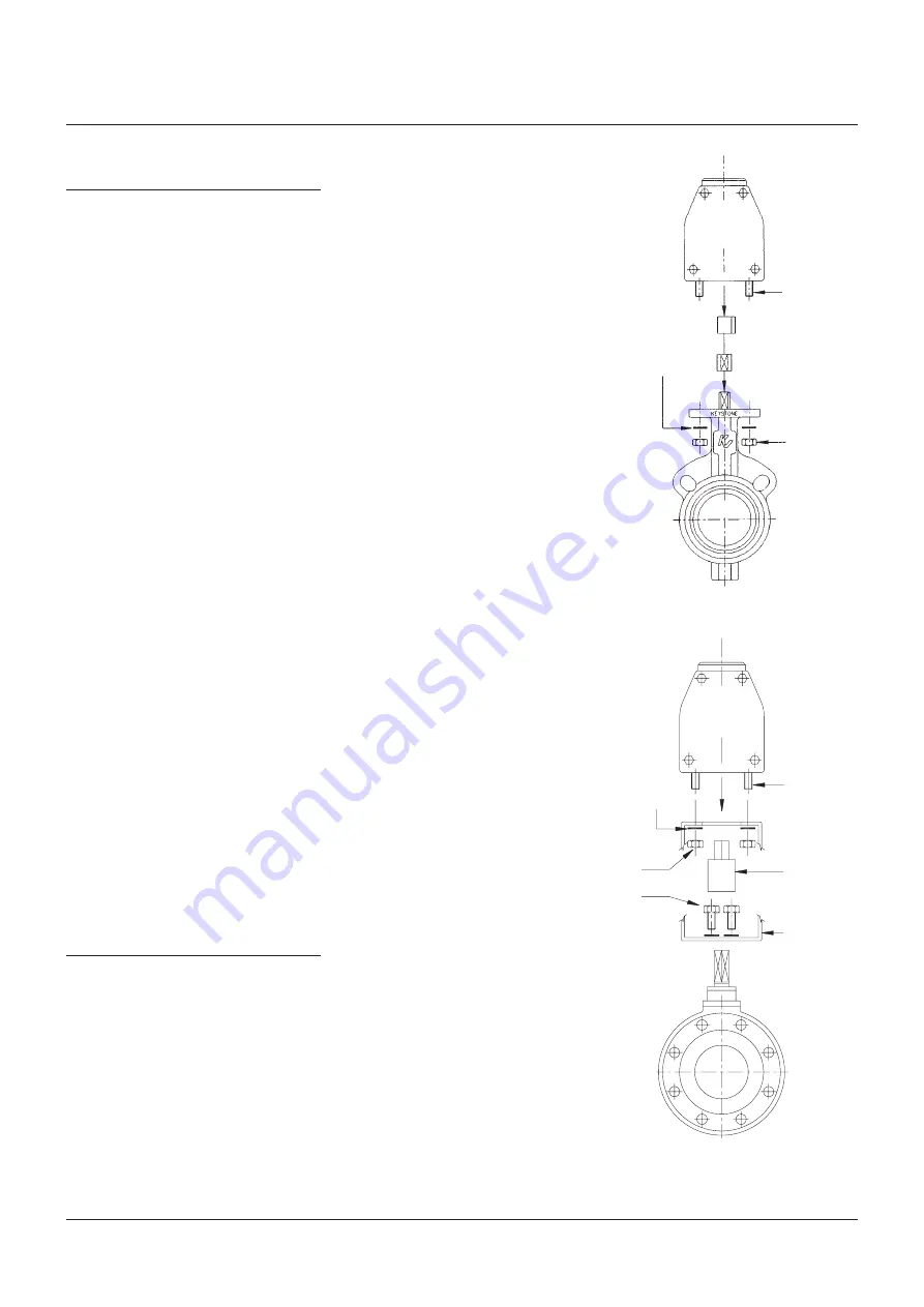
3. Install the correct adaptor, if required, into
the actuator (fig. 1 - direct mounting) or
install the correct coupling and bracketry,
if required, to the valve (fig. 2 - bracket
mounted option).
See Notes 1 & 2
4. Mount the actuator onto the valve flange or
the bracket and secure using a lockwasher
and nut on each mounting stud.
5. Before installing the valve/actuator
assembly in a piping system, the disc travel
should be verified.
6. When installing the valve/actuator assembly
into pipeline, ensure that the specific
instructions relating to the valve installation
are followed. For valves which need to be
fitted with the valve in a position other than
fully closed, it may be necessary to fit the
valve into the pipeline prior to mounting the
actuator to the valve. Rubber lined butterfly
valves are an example of this.
7. For valves which need to be installed in the
pipeline prior to fitting the actuator, ensure
that the valve is operated into its failsafe
position before mounting the actuator onto
the valve.
NON STANDARD INSTALLATION - DOUBLE &
SINGLE ACTING UNITS
In circumstances where the actuator is
required to be installed in the transverse
position i.e. at right angles to the valve bore
(Across Line), the actuator must be rotated
through 90°.
This is achieved in the following manner:
1. Remove the actuator from the valve or the
bracket by unscrewing the 4 fixing nuts and
withdraw it vertically from the valve.
2.
79U/E Models
- remove the double ‘D’
adaptor located in the bore at the bottom of
the actuator and re-fit, locating in previously
unused keyway of shaft.
NOTES
1. The adaptor should be lightly tapped or pressed
into the actuator.
2. The coupling should be lightly tapped or pressed
onto the valve stem.
Excessive force should not be used (the use of a
lubricant such as Coppaslip is recommended).
FIGURE 1
FIGURE 2
Pneumatic
actuator
Pneumatic
actuator
Ball
valve
Stud
Nut
Stud
Nut
Bolt
Valve
Adaptor
if required
Adaptor
if required
Coupling
if required
Bracket
if required
Lockwasher
Lockwasher
3. Refit actuator to the top of the valve. (note:-
on models 036/065/090 adaptors may not be
required to be fitted ie directly mounted, in
this case simply use the previously unused
keyway.)


