5
KEYSTONE
FIGURE 79 PNEUMATIC ACTUATOR
OPERATING AND MAINTENANCE INSTRUCTIONS
NOTES
Refer to notes on page 4 as indicated.
12. Fit ‘O’-ring seals (item 14) to endcaps (item
3) using a light smear of grease.
13. Fit endcap spring assemblies to body and
alternately tighten the endcap screws
(item 15) until secure (see recommended
torque table).
14. Fit position indicator to top of actuator.
15. Operate the actuator to OPEN & CLOSE
positions using compressed air and note the
actual positions. If the required travel is not
achieved refer to page 10.
Fail Open Units
7. Insert pistons (item 2) complete with
backing pads (1) (item 18) and backing rings
(4) as follows:-
- with piston legs on
right side
of bore
(when viewed from the o-ring end of the
piston), until racks engages with pinion and
then push fully inward, the actuator is now
in the fully open position.
Note:
If no travel stops are fitted proceed to
instruction 12.
8. Turn the pinion shaft clockwise
approximately 5° until it is orientated in line
with the major axis of the actuator body. The
shaft is now in the open position.
9. Insert Open travel stop bolt (item 19/20)
together with sealing nut or lock nut (2)(3),
flat washer (2)(3) and sealing washer (2)
(3) until the bolt hits the travel stop cam.
Tighten the lock nut.
10. Turn the pinion shaft clockwise through 90°
to bring it in line with the center line of the
actuator bore, the actuator is now in the
close position.
11. Insert CLOSE travel stop bolt (item 19/20)
together with sealing nut or lock nut (2)(3),
flat washer (2)(3) and sealing washer (2)
(3) until the bolt hits the travel stop cam.
Tighten the lock nut.
Fail Close Units
7. Insert pistons (item 2) complete with
backing pads(1)(item 18) and backing
rings(4) as follows:-
- with piston legs on
left side
of bore (when
viewed from the o-ring end of the piston),
until racks engages with pinion and then
push fully inward, the actuator is now in the
fully closed position.
Note:
If no travel stops are fitted proceed to
instruction 12.
8. Turn the pinion shaft anti-clockwise
approximately 5° until it is orientated in line
with the major axis of the actuator body. The
shaft is now in the closed position.
9. Insert CLOSE travel stop bolt (item 19/20)
together with sealing nut or lock nut (2)(3),
flat washer (2)(3) and sealing washer (2)
(3) until the bolt hits the travel stop cam.
Tighten the lock nut.
10. Turn the pinion shaft anti-clockwise through
90° to bring it back in line with the center
line of the actuator bore, the actuator is now
in the open position.
11. Insert Open travel stop bolt (item 19/20)
together with sealing nut or lock nut (2)(3),
flat washer (2)(3) and sealing washer (2)
(3) until the bolt hits the travel stop cam.
Tighten the lock nut.
ASSEMBLY - SINGLE ACTING UNITS
Note:
Please refer to the exploded views
further on.
Liberally grease actuator bore, pistons and
pinion assembly with Molyrace LT
lubricant.
Note:
The endcap spring assembly is a
complete module with the appropriate spring
preset to suit the selected duty parameters.
Spring retaining bolt threads are bonded to end
caps with threadlock sealant to ensure double
security.
Caution!
No attempt should be made to remove
or adjust spring retaining bolts.
1. Coat all ‘O’-ring seals with Molyrace LT
lubricant.
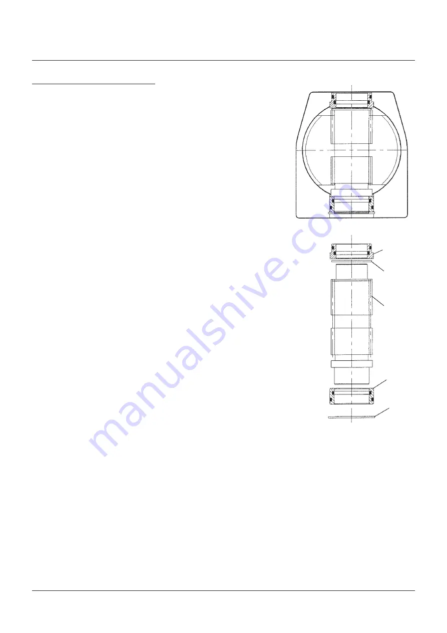
2. Output shaft assembly:-
a) Fit the top bearing assembly (item 9) into
the top bore of the actuator body (item 1)
with the outer o-ring uppermost.
b) Fit the bottom bearing assembly (item 6)
on to the bottom of the pinion shaft (item
5) with internal o-ring uppermost.
3. Insert pinion shaft assembly from underside
of the actuator as shown in the diagram
opposite.
4. Fit internal circlip (item 12) to bottom recess
of body to locate the shaft assembly.
5. Fit ‘O’-ring seals (item 13) on pistons (item 2).
6. Orientate output shaft at 45° ± 2°.
FIGURE 4
Sectioned assembly of actuator
body and output shaft
Top bearing
assembly
Gear shim as
required
See note 4
Output shaft
Bottom bearing
assembly
Internal circlip


