


Instruction Manual
D200149X012
3610J and 3620J Positioners
September 2017
38
2. Release all pressure from the positioner. Disconnect the supply, instrument, and output tubing.
WARNING!
If using gas as the supply medium, ensure adequate ventilation and remove any ignition sources.
3. Remove all gauges [key 79 (not shown), 80 and 81], pipe plugs (key 72 and 78), or tire valves (key 73, not shown)
from the gauge block (key 158).
4. Remove the two socket head screws (key 187) and remove the gauge block from the positioner case (key 115A,
figure 25). Inspect the four O‐rings (key 159) and replace if necessary. Apply lubricant (key 153) to the O‐rings
before replacement.
Disassembling the 3622 Electro‐Pneumatic Converter
Refer to figure 30 for key number locations while disassembling the converter.
Note
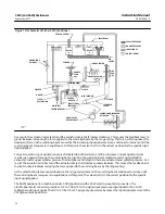
To check the operation of the electro‐pneumatic converter, remove the pipe plug nearest the converter (key 37, figure 30), and
connect a pressure gauge. Provide a 1.4 bar (20 psig) supply pressure to the positioner. For a 4 milliampere DC input signal, the
pressure gauge should read 0.17 to 0.23 bar (2.5 to 3.5 psig). For a 20 milliampere DC input signal, the pressure gauge should read
0.96 to 1.07 bar (14.0 to 15.5 psig).
1. Turn off electrical power to the converter. Release all supply pressure from the positioner.
2. Remove the cap (key 20), and disconnect the field wiring from the terminal block.
a. If a grounding wire is used inside the housing compartment, disconnect the wire from the interior housing
ground screw (key 31).
b. If an exterior grounding wire is used, disconnect the grounding wire from the external ground screw (key 31).
3. To remove the converter module, remove the two screws (key 30) and pull the module out of the housing. Inspect
the O‐ring (key 26) and replace it, if necessary.
a. If removing the 3622 electro‐pneumatic converter assembly from the pneumatic positioner, continue with steps
b. If replacing the converter module only, obtain a replacement converter module and refer to the Assembling the
3622 Electro‐pneumatic Converter procedure. If replacing the converter module, calibrate the pneumatic
portion of the positioner by performing the Calibration procedures after module replacement. There is no
converter module calibration.
4. Disconnect the supply tubing, output tubing, and conduit from the converter.
regulator from the converter assembly. Inspect the O‐ring (key 190, figure 27) and replace if necessary. Apply
lubricant (key 17) to the O‐ring before replacement.
6. Remove the two socket head screws (key 35) and remove the converter from the positioner case (key 115A,
figure 25). Inspect the four O‐rings (key 36) and replace them if necessary. Apply lubricant (key 17) to the O‐rings
before replacement.
Disassembling the Feedback Lever Assembly
Refer to figure 28 for key number locations, unless otherwise indicated, while disassembling the feedback lever
assembly.


