


Instruction Manual
D200149X012
3610J and 3620J Positioners
September 2017
13
Note
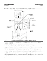
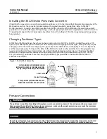
Cams A, B, and C have the letter D (direct acting) on one side. Always install the cam with the letter D on the same side as the cam
mounting screw heads (key 83, figure 3).
2. Uninstall the existing cam (key 82) from the actuator lever by removing the cam mounting screws (key 83).
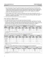
3. Install the desired cam (key 82) on the actuator lever with the cam mounting screws (key 83). Cams B and C use the
cam adjustment indicator (key 84) between the screw heads and the cam. Align the cam adjustment indicator with
the desired total valve rotation indication on the cam. Cam A does not use the cam adjustment indicator and does
not require adjustment.
CAUTION
To avoid parts damage, do not completely stroke the actuator while the actuator cover is removed.
WARNING
To avoid personal injury from moving parts, keep fingers and tools clear while stroking the actuator with the cover
removed.
4. Replace the actuator cover plate.
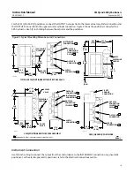
Mounting 3611JP and 3621JP on 585 and 585R Size 100 Actuators


