


Digitax ST User Guide
95
Issue: 5
It is expected that most systems will have the interpolation cycle time
equal to the drive synchronization interval. An interpolation cycle is
referred to as a profile cycle. The inter-operation between a profile cycle
when interpolation position mode is being used and the drive
synchronization interval is described as follows:
1. Interpolation cycle time = drive synchronization interval. In this case,
each new interpolation cycle will be synchronized to the drive
synchronization interval. Interpolation will be performed in each of
the subsequent control loop cycles until the next sync signal edge.
Command and feedback values which are handled cyclically will be read
at defined times in the cycle. Command values handled/used every
cycle (profile or control loop) will be cached from the object dictionary in
the 90 µs period at the beginning of that cycle.
Any feedback values read during a cycle will be scaled as appropriate in
that cycle, cached, and then written during the 90 µs period at the
beginning of the next cycle. Feedback values that change internally
between control loop cycles (but whose objects are only updated every
profile cycle) will be read from the last control loop cycle in the profile
cycle.
PDO data will be copied to and from the object dictionary (from and to
the sync manager memory areas) in the 90 µs period at the beginning of
every profile cycle. PDO data mapped to drive parameters (but not SM-
Applications PLC parameters or other parameters accessed using Inter-
Option Communications), will be written to those parameters in the 90 µs
period at the beginning of every control loop cycle.
9.24.3 EtherCAT interface protocol support
The following are supported:
•
Four Sync Managers. Two are used for the Mailbox Protocol (non-
cyclic data) and two are used for process data (cyclic data)
•
Distributed Clocks
•
CANopen over EtherCAT (CoE)
•
Ethernet over EtherCAT (EoE)
•
CMP protocol through Modbus RTU
9.24.4 Menu 61 - General The EtherCAT interface
Set-up
Parameter 1.00 shortcut
Table 9-108 Parameter 1.00 shortcut
This Parameter can be used as a shortcut to Pr
1.00
as DSP-402
objects do not permit access to parameter zero.
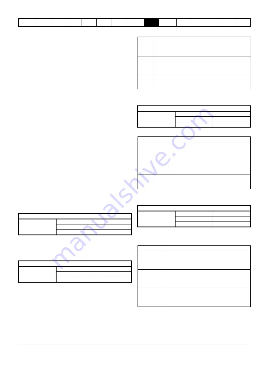
9.24.5 Drive synchronization control
Table 9-109 Drive synchronization control
Table 9-110 Synchronization control values
9.24.6 Inter-option module synchronization control
Table 9-111 Inter-option module synchronization control
Table 9-112 Inter-option module synchronization control values
9.24.7 Inter-option clock synchronization control
Table 9-113 Inter-option clock synchronization control
This parameter provides control of the inter-option module clock
synchronization mechanism.
Table 9-114 Inter-option clock synchronization control values
Parameter 1.00 shortcut
Pr
61.01
Default
0
Range
0 to 32767
Access
RW
Drive synchronization control
Pr
61.03
Default
1
Range
0 to 2
Access
RW
Value
Description
0
Independent.
The EtherCAT interface should not try to become
synchronization master to the drive.
1
Master with sync.
The EtherCAT interface should try to become synchronization
master to the drive only when fieldbus specific
synchronization has been achieved.
2
Master always.
The EtherCAT interface should always try to become
synchronization master to the drive.
Inter-option module synchronization control
Pr
61.04
Default
1
Range
0 to 2
Access
RW
Value
Description
0
Independent.
The EtherCAT interface should not try to become
synchronization master to other EtherCAT interfaces.
1
Master with sync.
The EtherCAT interface should try to become
synchronization master to other EtherCAT interfaces only
when fieldbus specific synchronization has been achieved.
2
Master always.
The EtherCAT interface should always try to become
synchronization master to other EtherCAT interfaces.
Inter-option clock synchronization control
Pr
61.05
Default
0
Range
0 to 2
Access
RW
Value
Description
0
Independent.
The EtherCAT interface should not try to be come
synchronization master to clocks in other EtherCAT
interfaces.
1
Master.
The EtherCAT interface should try to become
synchronization master to clocks in other EtherCAT
interfaces.
2
Slave.
The EtherCAT interface should become a
synchronization slave to clocks in another EtherCAT
interfaces.
Содержание Digitax ST
Страница 1: ...User Guide AC variable speed drive for servo motors Part Number 0475 0001 05 Issue 5 ...
Страница 209: ......
Страница 210: ...0475 0001 05 ...


