18
AGL_HP_ST_ZHK1P_EN_Rev00
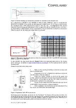
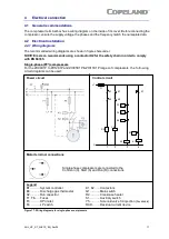
Three-phase compressors (TF*) with internal motor protection
For the ZH04K1P to ZH19K1P and ZHI05K1P to ZHI40K1P ranges of compressors t he f ollowing
circuit diagrams can be used:
Power circuit
Control circuit
L1
K1
K2
K1
K2
S1
P>
P<
F3
F4
B3
K2
R2
N
1
2
3
4
Y5
B1
K1
B1
F1
Motor terminal connections
Three-phase compressors are connected to the
T1, T2 and T3 connections
Legend
B1 ........... System controller
Q1 ......... Main switch
B3 ........... Discharge gas thermostat
R2.......... Crankcase heater
F1, F6, F8 Fuses
S1.......... Auxiliary switch
F3 ........... HP limiter
Y5.......... Solenoid valve for injection (
if available
)
F4 ........... LP switch
RCD....... Residual current device
K1, K2 ..... Contactors
Figure 18: Wiring diagrams for three-phase compressors with internal motor protec tion
Содержание COPELAND ZH04K1P
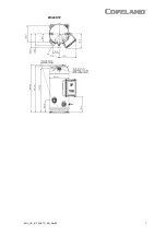
Страница 10: ...AGL_HP_ST_ZHK1P_EN_Rev00 7 ZHI46K1P ...

