16
U.L. Model No.: 42-ANT & 52-ANT
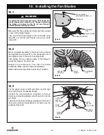
10. Installing the Fan Blades
RUBBER GROMMETS
BLADE FLANGE
ALIGNMENT
POST
M5 x 6 WASHER
HEAD BLADE SCREW (3)
FAN BLADE
Figure 22
10.1
Make sure the three rubber grommets are firmly seated
on each of the blade flanges.
Then mount the blade flanges to the fan blades using
three M5 x 6 washer head blade screws per blade
(Figure 22).
CAPTIVE
SCREW (2)
BLADE
FLANGE
ALIGNMENT
SLOT
MOTOR HUB
Figure 23
10.2
Mount one blade assembly to the motor hub by mating
the alignment post (Figure 23) of the flange with one of
the alignment slots in the motor hub (Figure 23).
Then tighten the two captive screws in the flange to
secure the flange to the motor hub.
Repeat this procedure for the other four blade
assemblies. Make sure all screws are tightened.
Spare captive screw provided in parts bag if needed.
CHAIN
COUPLER
WOODEN
PENDANT
3-SPEED
SWITCH
PULL CHAIN
LIGHT
FIXTURE
PULL CHAIN
WOODEN
PENDANT
Figure 24
10.3
Cut the speed control switch pull chain and the light
switch pull chain to the desired lengths.
Connect the wood pendants (supplied) to the pull
chains by sliding the pendants (small hole first) onto the
pull chains.
Then attach the chain couplings (supplied) to the end of
the chains and allow the pendants to fall down over the
couplings (Figure 24).
To reduce the risk of personal injury, do not bend the
blade flanges when installing the flanges, balancing
the blades, or cleaning the fan. Do not insert foreign
objects between rotating fan blades.
WARNING
!

