emaux 9023901 Скачать руководство пользователя страница 8

P7    INSTALLATION

5. INSTALLATION

5. 1 LOCATION

5. 2  PIPING

Incorrect  suction  design  is  one  of  the  main  causes  for  problems  appearing  during  the  pump  installations.  The 

suction tube is one of the installation's main components, and it should meet the following conditions in order to 

avoid future problems.

1. It should be as short and straight as possible.

2

.

The Diameter of the tube should not be smaller than the diameter of the pumps inlet.

3

.

The suction tube should be fully airtight, if not the entr y of air can cause de-priming of the pump

4

.

The suction tube should have its own means of support and should not cause tensions or strains to the pump's 

flange.

5

.

Minimize the use of elbows, valves, narrowing or choking sections etc. which dangerously increase head losses 

and can cause air pockets as well as entr y of air into the piping.

6

.

Each pump should have its own dedicated suction tube. If for unavoidable reasons it is necessar y to connect two 

or more pumps to a single collector, the collector should have the same diameter from the first to the last outlet 

and should be sufficiently sized to supply the same flow rate to all pumps.

The  pump  should  be  located  nearby  as  close  as  possible  the  pool  or  spa  to  reduce  friction  loss  and  improve 

efficiency. It is recommended at least 1.5 meter from pool water and 3 meters according to Canadian code.

1.  It  is  suggested  that 

APS550P  and  APS  750P 

with  self-priming  capacity  for  In  Ground  Pool  application. 

APS1000P and APS1500P should be installed Below Ground Level. 

2. The pump should be placed on a solid foundation that will not 

vibrate. It must be bolted down to reduce noise from vibration. 

The  area  should  be  well  drained  to  prevent  flooding  damage 

the motor.

3. Install the pump in a well thermal ventilated environment and 

to protect from excessive moisture.

Ensure  there  is  enough  clearance  for  pre-filter  basket  &  Lid 

open and motor ventilation.

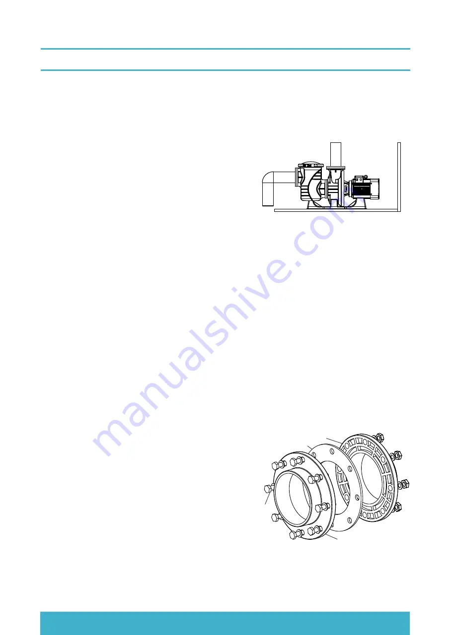
5. 3 FLANGE INSTALLATION

The  Pre-Filter  inlet  and  pump  body  discharge  outlet  are 

in  flange  type,  both  ANSI  (Class  150)  and  DIN  (PN10) 

standards are supported to share the same face and hole. 

1. Place the 8 large bolts from the pipe flange side to the 

pump.

2. Put a 3.2mm thickness gasket in between.

3. Push the bolts to the pre-filter flange hole. 

4. Keep the bolt straight and lightly snug each bolt with a 

wrench one by one until a squealing sound is heard to 

indicate that the bolts are being excessively tightened.  


Inlet or Outlet Flabge Face 

Gasket

Bolt Direction

Pipe Flange

Содержание 9023901

Страница 1: ...HYDRAU POWER PLASTIC PUMP APS SERIES OWNER S MANUAL Installation and Operation USER MANUAL Model APS Series EMPU22121601...

Страница 2: ...ER 6 3 VARIABLE FREQUENCY DRIVE VFD 6 4 SOFT STARTER 7 START UP 8 PRE FILTER BASKET MAINTIANCE 9 WINTERIZING 10 TROUBLE SHOOTING 11 TYPICAL INSTALLATION EXAMPLE 12 REPLACEMENT PARTS 13 TERMS OF THE WA...

Страница 3: ...e only 7 Switch OFF pump power before servicing and disconnecting the main circuit to the pump 8 Never change the filter control valve position while the pump is running RISK OF ELECTRICAL SHOCK COMPR...

Страница 4: ...bs or 1 2 A properly designed and tested suction limiting vent system or 1 3 An automatic pump shut off system 1 A SVRS meeting ASME ANSI A112 19 17 and or ASTM F2387 or 2 A properly designed and test...

Страница 5: ...lay with the appliance Cleaning and user maintenance shall not be made by children without supervision 3 The appliance shall be installed in accordance with national wiring regulations means for disco...

Страница 6: ...h Power KW 8 10 12 Noise dB 14 16 APS750P APS1000P APS1500P 4 5 5 7 5 11 72 72 68 68 95 130 90 120 210 270 82 110 185 260 75 105 180 250 65 90 160 240 50 80 135 210 APS550P PERFORMANCE CURVE 940 5 5HP...

Страница 7: ...ack of experience and knowledge unless they have been given supervision or instruction concerning use of the appliance in a safe way and understand the hazards involved Children must not play with the...

Страница 8: ...mps The pump should be located nearby as close as possible the pool or spa to reduce friction loss and improve efficiency It is recommended at least 1 5 meter from pool water and 3 meters according to...

Страница 9: ...the problem corrected by a qualified service representative before using Press the reset button to reset the RDC GFCI devices after fixed It will keeps the circuit shut off and will not reset if the p...

Страница 10: ...ine Starter that include 1 Motor Circuit Breaker is a short circuit magnetic protection devices 2 Control unit for Run and Stop operation and status monitoring 3 Protection relay is an overload therma...

Страница 11: ...he pump body to show the right direction Turn on the pump in one second and check the motor rotation direction is correct or not The motor will rotate in Clock wise direction if any two cables are int...

Страница 12: ...ble frequency driver for better starting and energy saving purpose The connection is simple it is just connect the 3 phase output of the variable frequency drive to the pump in Delta or Star configura...

Страница 13: ...que transients associated with electro mechanical reduced voltage starters 2 Voltage or current is applied gradually without the voltage and current transients associated with electro mechanical reduc...

Страница 14: ...ear all piping of construction debris and verify that the piping has passed a proper pressure test 2 Check the filter and other equipment for proper installation verifying all clamps and connections a...

Страница 15: ...the lid O ring if damaged replace Turn off the pump at the breaker Close the inlet and discharge valves Discharge the water by drain on the pre filter bottom Release the two Lid fastener of the neck c...

Страница 16: ...of 3 Phase Circuit 5 Pump Shaft rotating in wrong direction 10 TROUBLE SHOOTING Problem Corrective Action Pump Will Not Prime 1 No water in Pre filter Lid is not tight Damaged lid O Ring 2 Water level...

Страница 17: ...tion of the pump so as to prevent the draining off of the water outlet pipe after the pump is stopped The soft connection can prevent the forming of cavitation Pressure gauge can check the working pre...

Страница 18: ...0HP 15HP Pre Filter Body APS5 5HP 7 5HP Pre Filter Body APS10HP 15HP Drain Plug Ding Qing O ring O ring APS5 5HP 7 5HP O ring APS10HP 15HP 1 1 1 1 2 2 1 1 9 420336559 420336556 Pump Body APS5 5HP 7 5H...

Страница 19: ...eriod begins on the day of purchase and extends only to the original purchaser It is not transferable to anyone who subsequently purchases the product from you It excludes all expendable parts During...

Страница 20: ...YOUR PREMIER SUPPLIER www emauxgroup com EMAUX WATER TECHNOLOGY CO LTD...

Отзывы: